
Image display apparatus, and disguising device

a technology of image display and display luminance, which is applied in the field of image display apparatus and disguising device, can solve the problems of affecting the acceptance of consumers' homes, the non-aesthetic appearance of display apparatuses when not in use, and the negative effect of image quality and display luminan

Active Publication Date: 2010-01-21
TOP VICTORY INVESTMENTS
View PDF11 Cites 26 Cited by
  • Summary
  • Abstract
  • Description
  • Claims
  • Application Information

AI Technical Summary

Benefits of technology

"The invention relates to a display device that can be used in a disguising effect, meaning it can be used to hide the image display when the display is turned off. The device includes a scattering layer that scatters the ambient light and a reflective member that reflects a portion of the scattered light in a specific direction. The reflective member is placed between the scattering layer and the display device, and its reflectivity is preferably high to improve the disguising effect. The scattering layer can be controlled to scatter the ambient light in a specific way, and the reflective member can be switched on or off simultaneously with the display device. The device can be used in various embodiments, such as an active scattering layer or a scattering polarizer. The invention also provides a method for controlling the amount of scattering in the scattering layer."

Problems solved by technology

A major complaint with respect to especially large display apparatus is their non-aesthetic appearance when they are not in use.
This hinders acceptance in consumers' homes.
When investigating various types of materials it was found that currently commercially available scattering layers (PDLC, CTLC, polymer network LC based) do not offer sufficient hiding power to make the display device substantially invisible in its off state under the condition that the display device and the scattering layer are in relatively close contact.
However, the drawback of increasing the thickness of this scattering layer is an increase in the driving voltage.

Method used


Image

  • Image display apparatus, and disguising device
  • Image display apparatus, and disguising device
  • Image display apparatus, and disguising device

Examples


Embodiment Construction

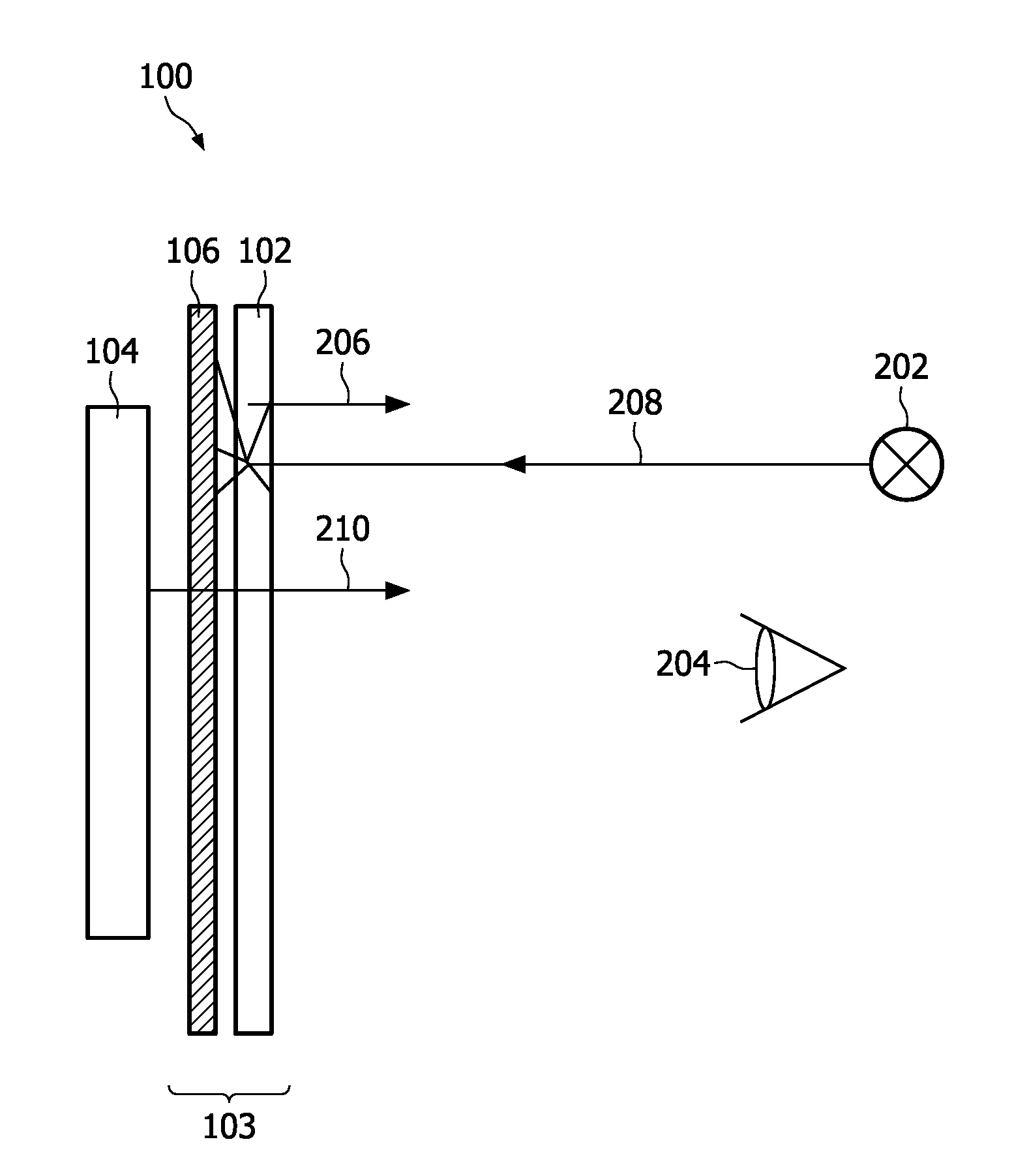
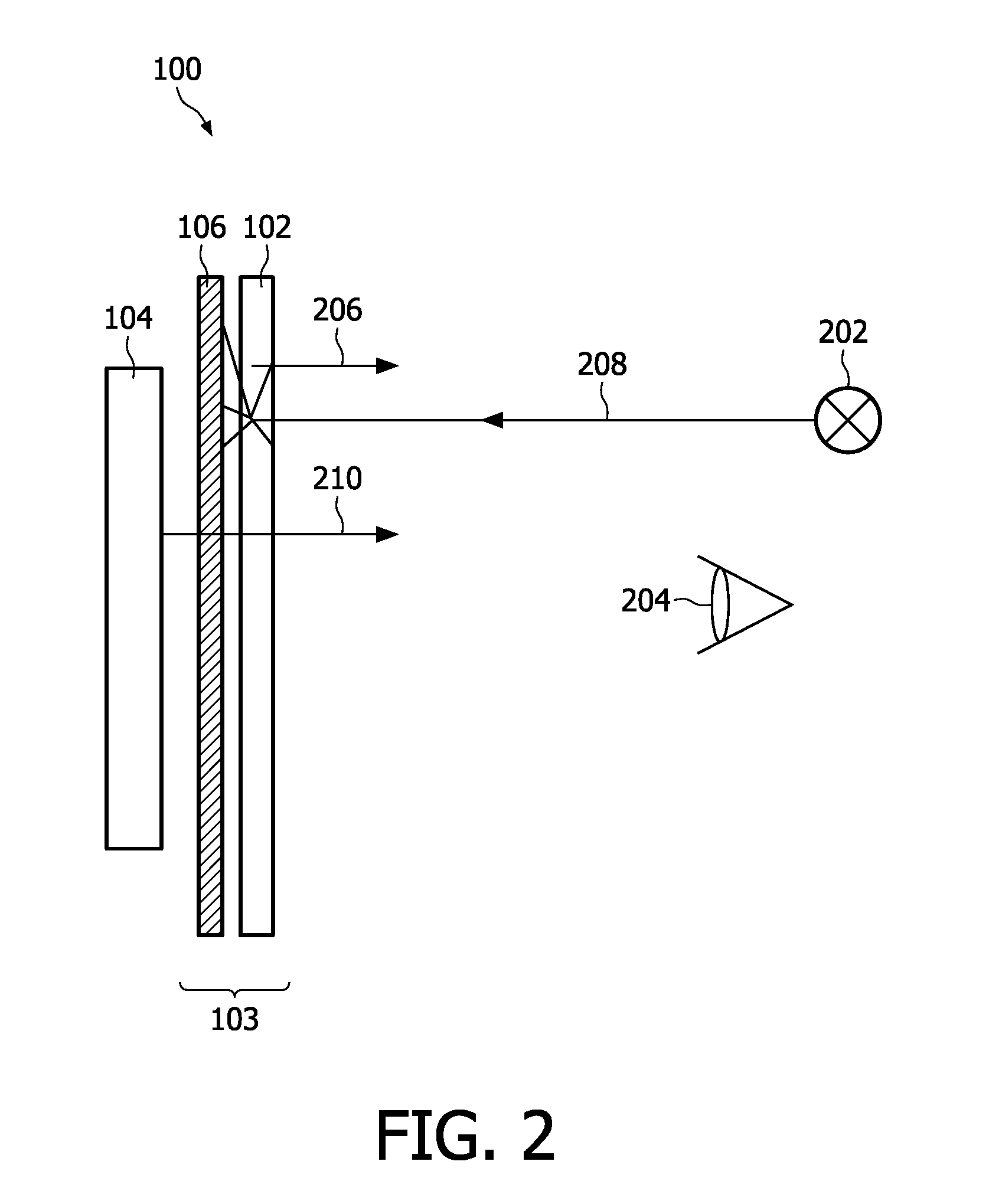
[0045]FIG. 2 schematically shows a side view of an image display apparatus 100, comprising a display device 104 and a disguising device 103 arranged in front of the display device 104, which disguising device 103, in this embodiment, comprises a scattering layer 102 and a reflective member 106. A viewing person is schematically indicated at 204. The display device 104 is arranged for displaying an image, by emission of display light 210 in a first direction, i.e. from the display device 104 towards the viewing person 204. An ambient light source 202 generates ambient light 208. The scattering layer 102 is arranged for scattering a portion of the ambient light 208. The reflective member 106, which is located behind the scattering layer 102 as seen from the viewer 204, is arranged for reflecting a portion of the scattered ambient light 206 into the first direction.

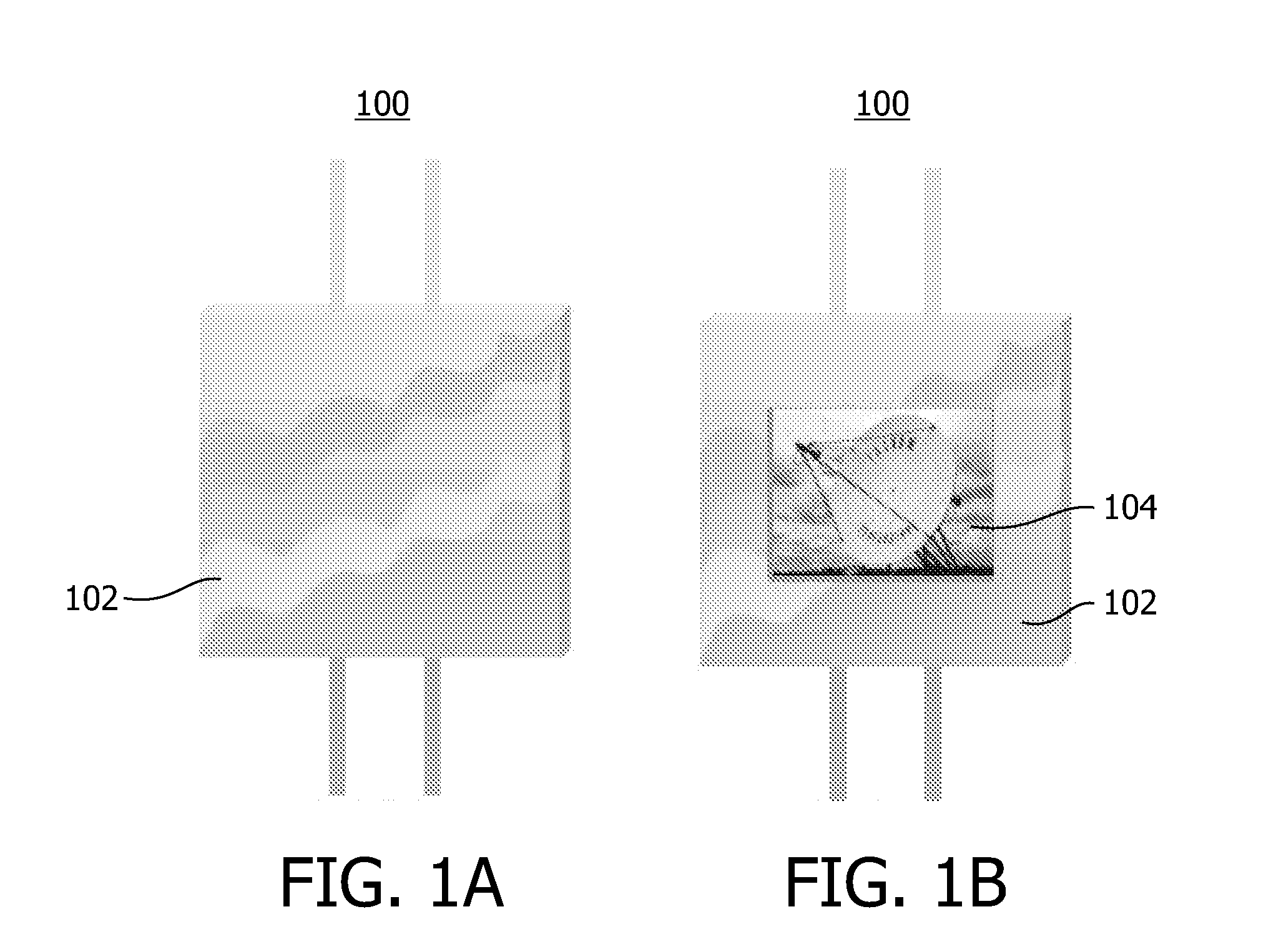
[0046]FIG. 1A shows a front view of the image display apparatus 100 when the display device 104 is turned off. Basically, ...


PUM


Abstract

An image display apparatus (100) comprises: a display device (104) for displaying an image 900 by emission of display light (210) in a first direction; a scattering layer (902) disposed in front of the display device (104), for scattering at least a portion of ambient light (208); a transparent plate-shaped light source (950), arranged parallel to the scattering layer (902) and being optically coupled to the scattering layer (902). The plate-shaped light source (950) may be a passive light source, in which case at least one light source (967) is arranged along an edge of the plate-shaped light source (950). When the display device (104) is ON, the scattering layer (902) and the plate-shaped light source (950) are transparent. When the display device (104) is OFF, the scattering layer (902) is scattering and the plate-shaped light source (950) is ON.

Description

FIELD OF THE INVENTION[0001]The present invention relates in general to an image display apparatus comprising a display device and a disguising device disposed in front of the display device. The present invention also relates to a disguising device.BACKGROUND OF THE INVENTION[0002]Image display apparatus comprising a display device are known. Conventional examples of a display device include cathode ray tube type of image screen, more recent developments include LCD screens, plasma screens, etc. A major complaint with respect to especially large display apparatus is their non-aesthetic appearance when they are not in use. This hinders acceptance in consumers' homes. It is within the philosophy of some designers and interior architects to develop concepts where the display device is disguised by a static or dynamic architectural object. In other words unobtrusive design is considered to be relevant.[0003]Ambient displays is the overall name for display apparatus that can display inf...

Claims


Application Information

Patent Timeline
Patent Type & Authority Applications(United States)
IPC IPC(8): F21V13/10
CPCG02B6/0035H04N5/72G02B6/0055G02B6/0051
Inventor OVERSLUIZEN, GERRITDE KONING, HENDRIKVAN RIJSWIJK, RONALDHORNIX, EEFJE JANET
Owner TOP VICTORY INVESTMENTS
Learn More