Optimized Dynamic Routing in a network, in particular in an optical telecommunication network

a dynamic routing and optical telecommunication technology, applied in the field of dynamic routing in the network, can solve the problems of high block probability in congested networks, inability to adapt to transparent networks, and inability to reduce costs so effectively, so as to achieve the lowest run-through cost, the effect of reducing the cost of operation and reducing the cos

Active Publication Date: 2010-01-21
TELECOM ITALIA SPA
View PDF4 Cites 55 Cited by
  • Summary
  • Abstract
  • Description
  • Claims
  • Application Information

AI Technical Summary

Benefits of technology

[0018]The objective of the present invention is to provide a dynamic routing that optimizes the exploitation of a WDM translucent network, in particular the utilization of the valuable network resources, e.g. by minimizing usage of OEO converters and / or wavelength converters, that guarantees the feasibility of a path from a signal impairment point of view, and that is flexible enough to follow variable traffic pattern and to adapt to changes in the network topology (e.g. deployment of new equipment).
[0026]searching for a second set of paths including the paths between each couple of second nodes that pass only through first nodes and have associated therewith a run-through cost lower than the predetermined cost;
[0033]searching for a fourth set of paths including the paths between the given node and the first nodes that pass only through first nodes and have associated therewith a run-through cost lower than a predetermined cost.
[0037]searching for a path having the lowest run-through cost from the given node to the destination node in both the fourth set of paths and the enhanced network topology.
[0040]selecting the path in the enhanced network topology having the lowest run-through cost from the given node to the destination node, and

Problems solved by technology

This is acceptable in a regenerating network, i.e., a network with OEO converters, but may not be suitable in a transparent network, i.e., a network without OEO converters.
In connection with US2003 / 0016414, the Applicant has observed that the proposed solution may result in high block probability in congested networks, since the feasibility of a path is determined only “a posteriori” and therefore cannot be guaranteed.
Moreover cost reduction could be not so effective due to the adopted network model that needs OEO conversion in all the nodes of the network.

Method used


Image

  • Optimized Dynamic Routing in a network, in particular in an optical telecommunication network
  • Optimized Dynamic Routing in a network, in particular in an optical telecommunication network
  • Optimized Dynamic Routing in a network, in particular in an optical telecommunication network

Examples


Embodiment Construction

[0072]The following discussion is presented to enable a person skilled in the art to make and use the invention. Various modifications to the embodiments will be readily apparent to those skilled in the art, and the generic principles herein may be applied to other embodiments and applications without departing from the spirit and scope of the present invention. Thus, the present invention is not intended to be limited to the embodiments shown, but is to be accorded the widest scope consistent with the principles and features disclosed herein and defined in the attached claims.

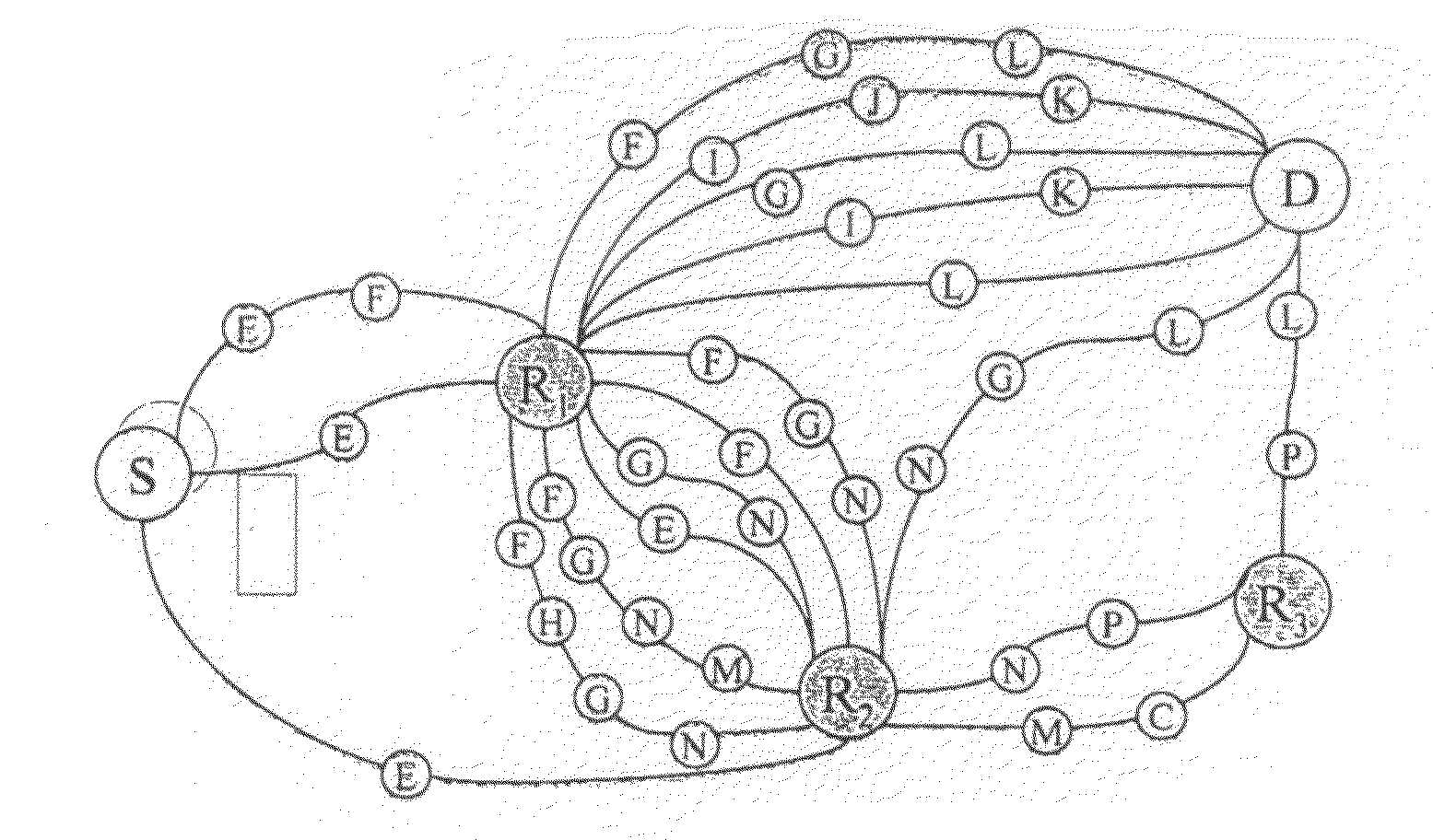
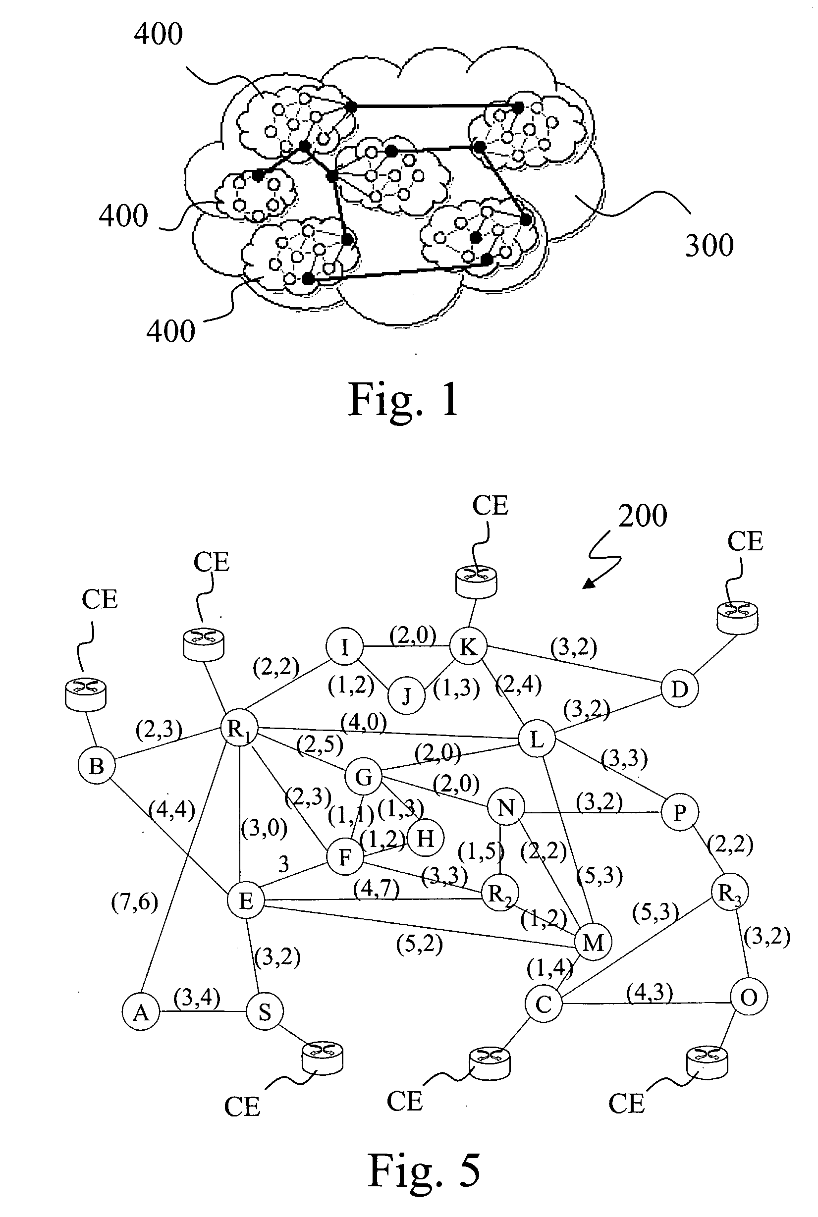
[0073]The dynamic routing according to the present invention will now be described with reference to an arbitrary translucent network of the type shown in FIG. 5, i.e. a translucent network 200 based on at least two different network nodes. Preferably the two types of nodes are the following:[0074]signal regenerating nodes, or “opaque” nodes, depicted in FIG. 5 as grey circles, and designated by the letter R; ...


PUM


Abstract

A routing method for a network including a first type of nodes and a second type of nodes, in particular an optical telecommunication network including transparent codes and regenerating nodes, includes: constructing a simplified network topology including the given node, the second nodes, first paths between the given node and the second nodes and second paths between each couple of second nodes, wherein the first and second paths pass only through first nodes and have an acceptable run-through cost, and, if the given node receives a routing request specifying a destination node that is reachable only through a second node, constructing an enhanced network topology by adding to the simplified network topology the destination node and third paths between the destination node and the second nodes that pass only through first nodes and have an acceptable run-through cost; and searching for a path having the lowest run-through cost from the given node to the destination node in the enhanced network topology.

Description

TECHNICAL FIELD OF THE INVENTION[0001]The present invention relates in general to dynamic routing in a network. In particular, the present invention finds an advantageous, but not exclusive, application in optical telecommunication networks, particularly wavelength-switched and waveband-switched optical telecommunication networks, such as Wavelength Division Multiplexing (WDM) or Dense Wavelength Division Multiplexing (DWDM) optical telecommunication networks, to which the ensuing description will refer, without this implying any loss of generality. In fact, the core concept of the present invention may also be applied equally well to completely different contexts where the best path between two points has to be found according to given criteria, for example signal routing in a semiconductor chip, parcel delivery by post service (DHL, UPS, FedEx, etc.), traffic planning, etc.BACKGROUND ART[0002]As is known, in the last years one of the key elements in telecommunication networks has ...

Claims


Application Information

Patent Timeline
Patent Type & Authority Applications(United States)
IPC IPC(8): H04J14/00H04L12/26H04L12/28
CPCH04J14/0284H04Q2011/0084H04Q2011/0086H04J14/0269H04J14/0257H04J14/0267H04J14/0246
Inventor D'ALESSANDRO, ALESSANDROMORRO, ROBERTOSANTOS, VICTORIA SALMERON
Owner TELECOM ITALIA SPA
Why Eureka
Try Eureka