Positive displacement pump apparatus

a pump and positive displacement technology, applied in mechanical devices, flexible wall reciprocating engines, couplings, etc., to achieve the effect of higher displacement energy

Inactive Publication Date: 2010-01-21
WEIR MINERALS NETHERLANDS BV
View PDF9 Cites 1 Cited by
  • Summary
  • Abstract
  • Description
  • Claims
  • Application Information

AI Technical Summary

Benefits of technology

[0009]wherein the one or more pump chambers are connected via at least one intermediate fluid chamber with at least one displacement element, the displacement element being arranged to alternately carry out a suction stroke and a displacement stroke during its movement so as to displace fluid in the intermediate fluid chamber, which thereby increases and reduces, respectively, the volume of the pump chamber;
[0011]wherein according to the invention a force means is provided for applying force or energy to a side of said at least one displacement element at least during the displacement stroke, in such a manner that said force or energy counteracts the force exerted on the displacement element by the fluid in the intermediate fluid chamber, thereby reducing the overall force needed to carry out the displacement stroke movement of the displacement element.
[0014]As a result of the exertion of an additional force on the displacement element, the load to which the various parts are subjected during operation of the displacement device can be greatly reduced.
[0019]In a further alternative embodiment, the force means can comprise a gas-biased accumulator for a working medium, which accumulator is in communication with a side of the displacement element which is opposite to the side on which the pump chamber is located. In this way a counterpressure or an opposing force can be exerted on the displacement element in an effective manner, in particular during the displacement stroke, resulting in reduced forces or loads on the moving parts of the apparatus. In one form of this, the working medium may be a pressurisable fluid, in particular a gas. In such an embodiment the accumulator can function as a reservoir for fluid which is displaced into and out of the accumulator depending on the position of the displacement element.

Problems solved by technology

As a result of this unbalanced application of forces, the constructional dimensions of the displacement element and its respective parts are geared to the loaded displacement stroke.

Method used


Image

  • Positive displacement pump apparatus
  • Positive displacement pump apparatus
  • Positive displacement pump apparatus

Examples


Embodiment Construction

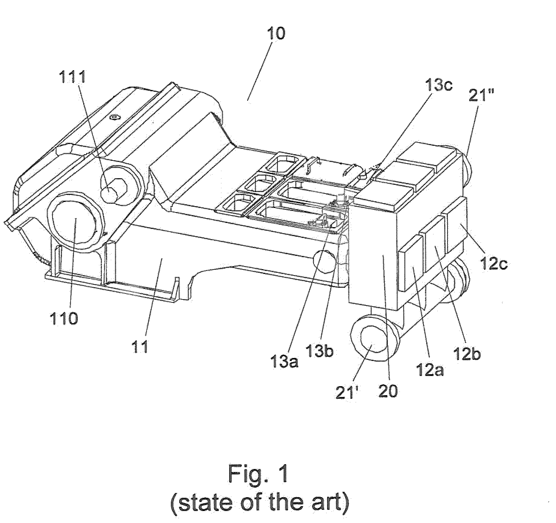
[0040]For a correct understanding of the invention, like parts will be indicated by the same numerals in the description of the figures below. FIG. 1 shows an embodiment of a positive displacement pump according to the state of the art. The pump 10 comprises three pump chambers 12a-c, which are integrated in a pump housing 12 connected to the crankcase 11.

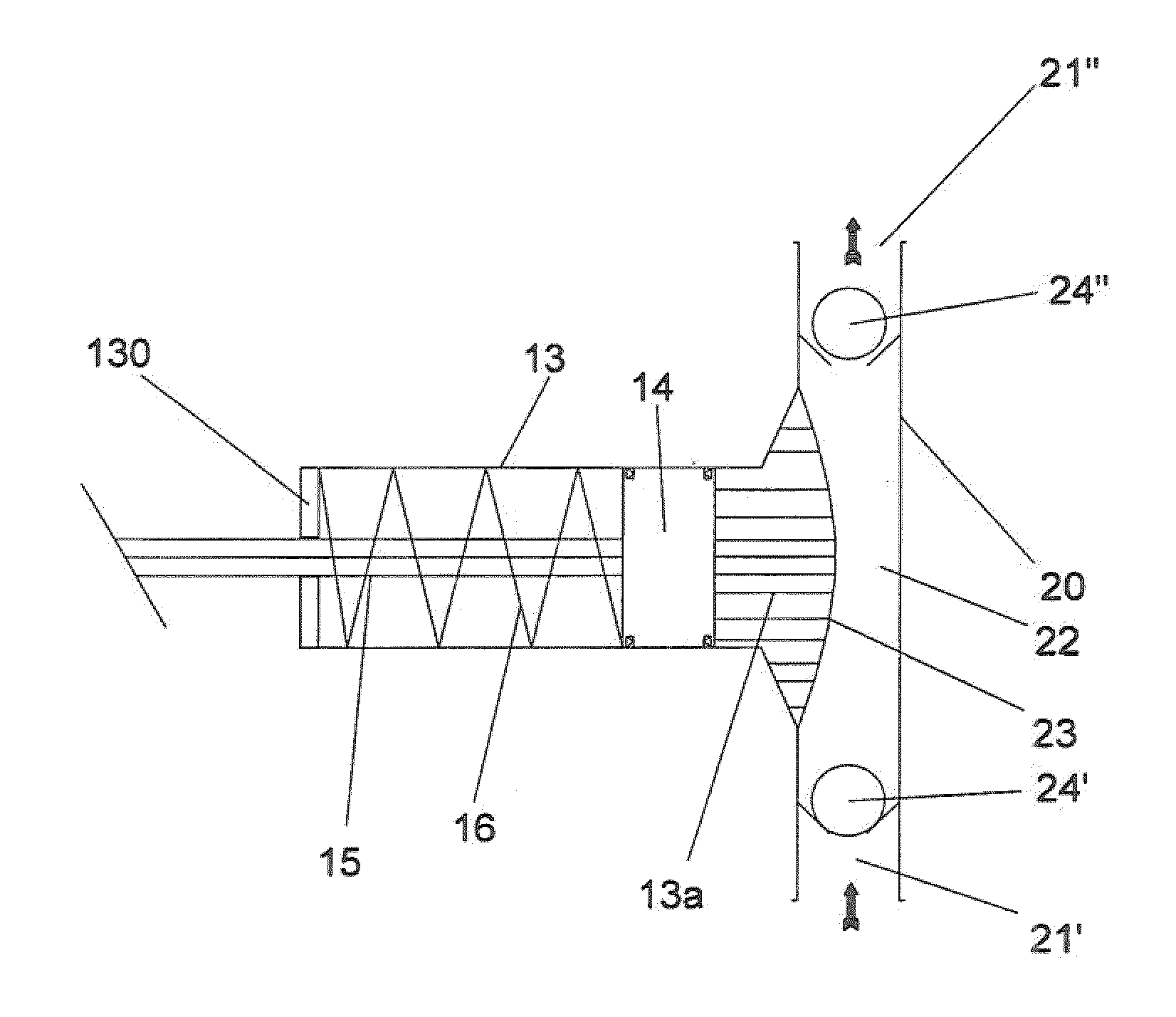
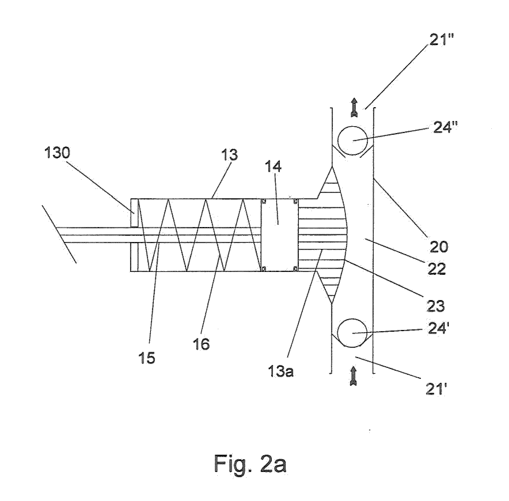
[0041]The positive displacement pump 10 is configured as a triple displacement device in this case. In this embodiment, the pump chamber 12 comprises three pump sections configured as cylinder-piston combinations, the individual cylinders of which are indicated 13a-13c. Positioned within the cylinder chambers 13a-13c are three pistons 14a-14c (not shown), which function as displacement elements. As shown, each piston 14a-14c is connected to a piston rod 15a-15c (see FIGS. 3 and 4), which piston rod 15a-15c is connected to some type of driving means. In this embodiment the driving means is configured as a crankshaft mounted for rota...


PUM


Abstract

A positive displacement pump apparatus (10) is disclosed for displacing a pumping fluid. The apparatus comprises one or more pump chambers (22) arranged in a pipe system for receiving the pumping fluid, the pipe system having at least one inlet (21′) which can be shut off by means of a valve (24′), and at least one outlet (21″) which can be shut off by means of a valve (24″). The one or more pump chambers 22 are connected via at least one intermediate fluid chamber (13″) with at least one displacement element in the form of a piston head (14) and a piston rod (15), which is arranged to alternately carry out a suction stroke and a displacement stroke during its movement so as to displace fluid in the intermediate fluid chamber (13″), which thereby increases and reduces, respectively, the volume of the pump chamber (22). At least one flexible separating element in the form of a diaphragm (23) is provided at the pump chamber (22) to separate the fluid in the intermediate fluid chamber (13″) from the pumping fluid. Furthermore, a force means is provided for applying force or energy to a side of said at least one piston head (14) at least during the displacement stroke, in such a manner that said force or energy counteracts the force exerted on the piston head (14) by the fluid in the intermediate fluid chamber (13″), which can thereby reduce the overall force needed to carry out the displacement stroke movement of the piston head (14) and a piston rod (15).

Description

TECHNICAL FIELD[0001]A positive displacement pump apparatus is disclosed for the pumping of media such as liquids or gases. Also disclosed herein is a method of controlling the operation of a positive displacement pump. It should be appreciated that the method and apparatus can be applied to many different designs of positive displacement pump including multiple chamber pumps.BACKGROUND ART[0002]Positive displacement pumps are widely used. Such pumps can comprise one or more pump chambers, each chamber having an inlet and an outlet. In use, the inlet and outlet can be sequentially opened and closed. In the known apparatus each pump chamber may be arranged with at least one displacement element, which can be moved by some sort of driving means arranged adjacent to the pump chamber. During its movement, the displacement element alternately carries out a suction stroke and a displacement stroke thereby increasing and reducing, respectively, the volume of the pump chamber.[0003]In some ...

Claims


Application Information

Patent Timeline
Patent Type & Authority Applications(United States)
IPC IPC(8): F04B43/067F04B9/02F04B17/00
CPCF04B9/02F04B43/067F04B17/03F04B17/00
Inventor WILMSEN, ARNOLDUS GERTRUDIS HENDRIKUS
Owner WEIR MINERALS NETHERLANDS BV
Why Eureka
Try Eureka