Rotary internal combustion engine

a technology of internal combustion engine and piston engine, which is applied in the direction of rotary piston engine, rotary or oscillating piston engine, engine lubrication, etc., to achieve the effects of improved general performance of the engine, excellent sealing, and distinct durability

Inactive Publication Date: 2015-05-12
BITTENCOURT JOSE FERNANDO
View PDF18 Cites 2 Cited by
  • Summary
  • Abstract
  • Description
  • Claims
  • Application Information

AI Technical Summary

Benefits of technology

[0033]The present application seeks to provide an improved Wankel rotary engine and additionally provides: a) Equivalent and / or improved general performance of the engine; b) Distinct durability due to a limited wearing of its component parts (movable or static), excellent sealing among the chambers, which significantly reduces the mechanical losses and provides excellent internal cleaning; c) For items “a” and “b”, respectively, a reduction in the cost and frequency of maintenance, both preventative and corrective; d) Reduction of the combustible consumption whether it be petroleum-based or bio-combustible, mainly alcohol (from sugar-cane, corn or similar sources); e) Minimization of the emission of pollutant gases and particulate matter in the atmosphere; f) A greater flexibility of engine specifications, where the same one is adequate for any type of engineering specification, in accordance with the engine application; and g) Equivalent or lower industrial cost when compared to commercialized rotary engines, since the same materials, machines and tools are used in the manufacturing of its component parts.
[0039]The synchronized translation and rotation movements of the rotor make it deviate and bring it near to the internal face of the jacket, increasing and reducing the volume of the chambers, for each 90°-angle turn of the rotor.

Problems solved by technology

a) Two-stroke-cycle engine: an engine that provides high rotation and, consequently, high power. Its operation may be understood by the two-stroke-cycle necessary to conclude a complete turn of the crankshaft. A disadvantage of this type of engine is that to obtain high power, it has a high consumption of combustible fuel. This results in a high emission rate of toxic gases and particulate matter in the atmosphere, which makes this type of engine unsuitable for use in ecologically friendly products.
b) Four-stroke-cycle engine: provides high power at relatively low rotations, when compared to the two-stroke-cycle engine, but its manufacturing requires a great number of static and dynamic parts. Its operation requires two complete turns of the crankshaft to complete a cycle. Despite being more economical from a point of view of fuel consumption, these engines present a high vibration level, high mechanical losses, as well as a great number of component parts, which means this type of engine has higher manufacturing costs, as well as high maintenance costs and a high probability of failure.
c) Diesel engine: this type of engine operates based on the absorption of atmospheric air inside the combustion chamber, where its internal temperature is increased to more than 600° C., and where the combustible (diesel) is directly injected inside the chamber and starts the explosion process. Contrary to piston rotary engines, and non-diesel two-stroke-cycle and four-stroke-cycle engines, this type of engine does not need a spark system to start the combustion process. However, they produce a high emission rate of gases and particulate matter in the atmosphere. They also present very intensive vibrations and they necessarily need a construction that makes them heavy and noisy, mainly due to the high compression rates.
d) Rotary engine: this type of engine has a simpler design compared to piston rotary engines. A rotary engine has a rotor (or rotors) that rotates inside a jacket. Rotary engines are generally extremely compact and light. However, application to vehicles has faced regulatory restrictions largely due to its combustible fuel consumption and pollutant emission rates.
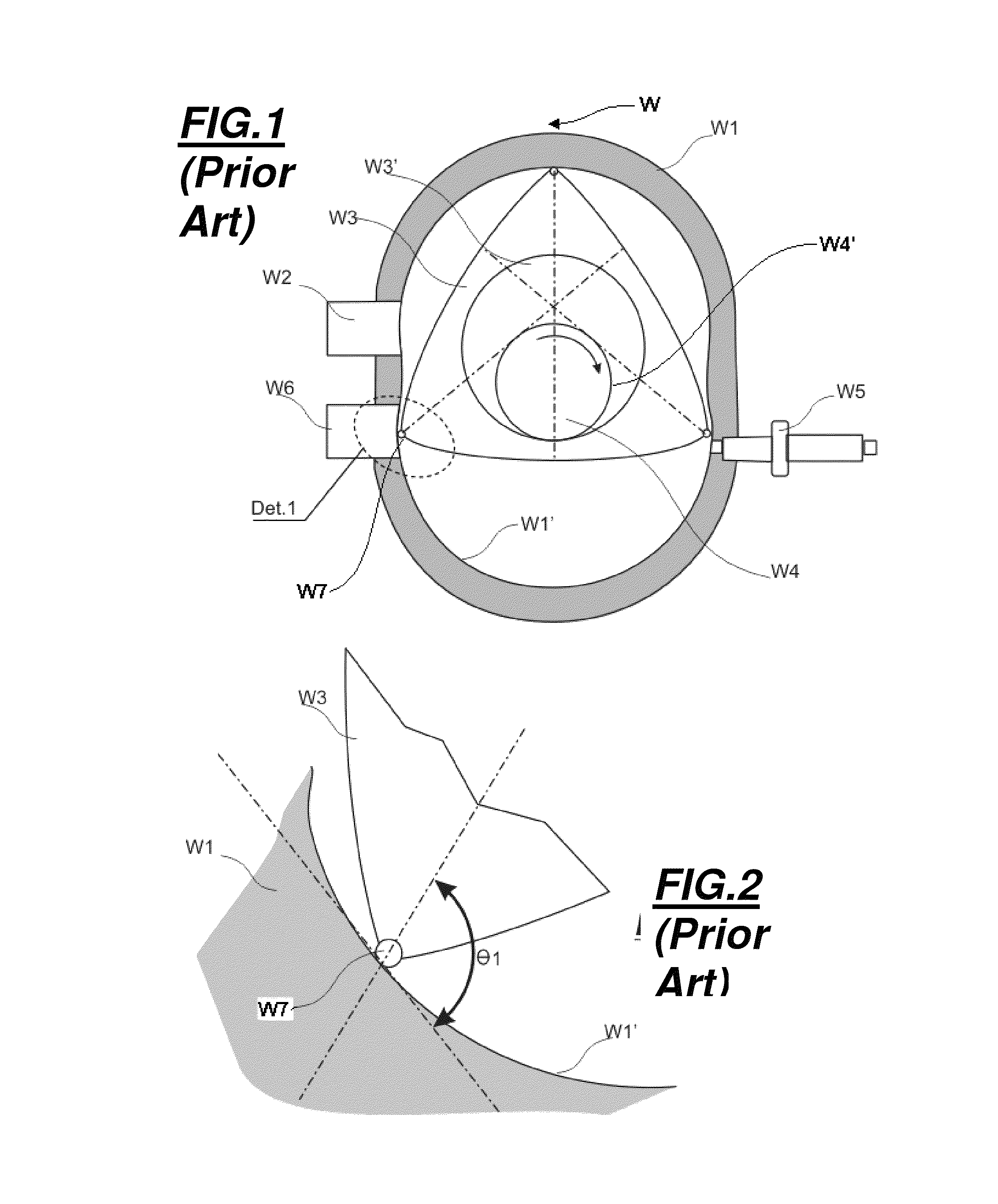
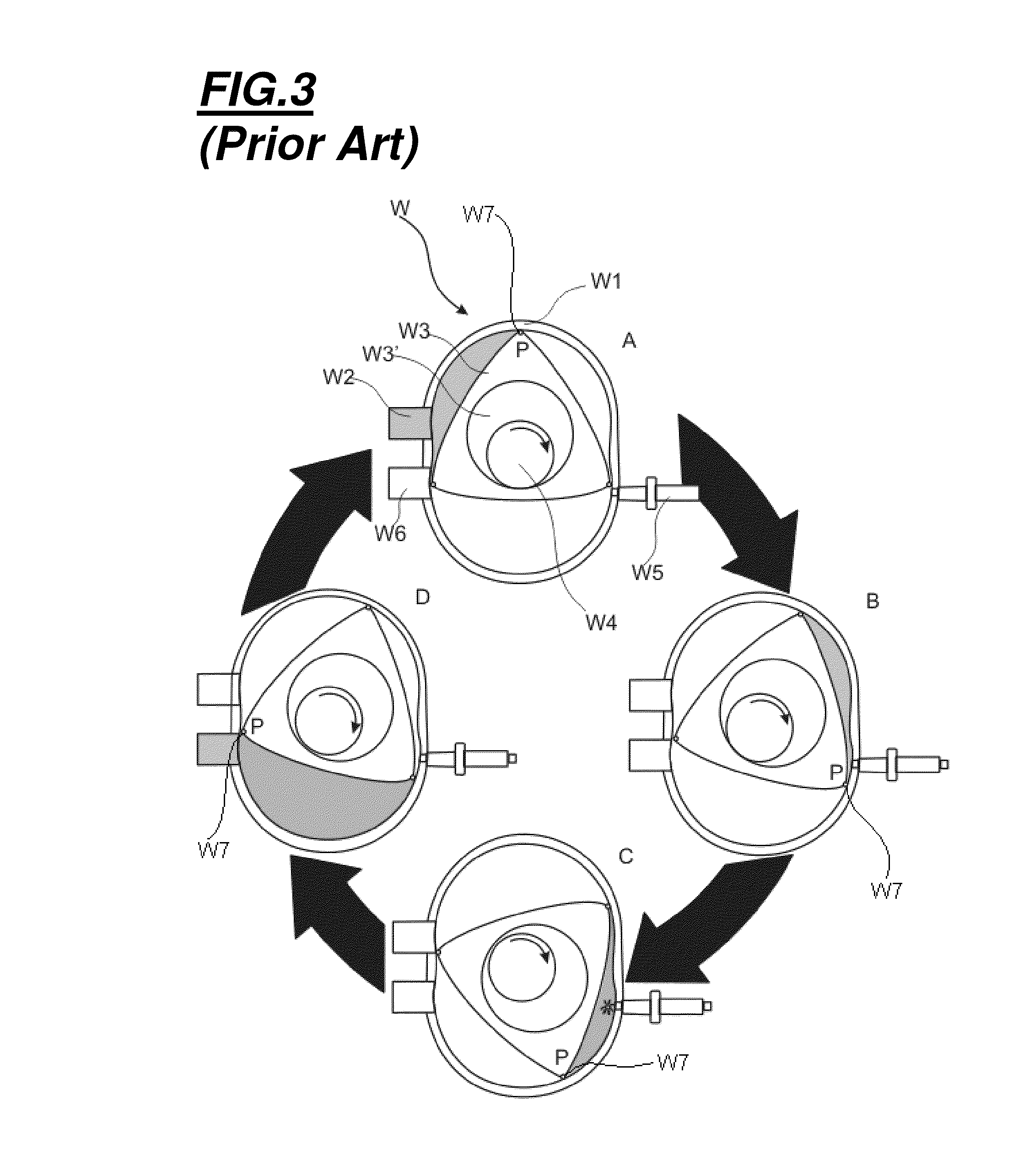
We can observe generally, that all these “Wankel” engines present the same problem of non-constant perpendicularity between the chamber divisors and the jacket.
This considerably impairs the sealing and internal cleaning, which results in a dirty and non-economical engine, that prevents the large scale production of these engines.
This eccentric displacement of the triangular rotor results in an increase or decrease of the space between the convex sides of the rotor and the wall of the cavity of the jacket.
Disadvantages of the Wankel rotary engines: Wankel rotary engines present the following negative characteristics:Impairment of their reliability due to deficient sealing systems on the edges of the triangual rotor and walls of the cavities of the chamber (jacket);Impairment of the durability due to its deficient sealing between static (jacket) and movable (rotor triangular / sealing) components that results in the formation and accumulation of particulate matter;Excessive engine heating due to the great internal area of the chamber, resulting in great heat exchange between the hot gas and the housing (jacket);A limited number of chambers and a unique possible relation between the fixed gear and the dynamic gear, fixed to the rotor; andIt necessitates a high-precision assembly of the involved components, with very restrictive tolerances—practically nominal measures.
However, it is a fact that these solutions present deficient aspects, mainly the obtainment of distinct reliability, durability and quality.
Current rotary engines have a deficient sealing system between the chambers, i.e., their form does not allow an ideal operation of the seals that separate the chambers, impairing the sealing at the contact point among the static and dynamic components of the engine.
Thus, there are moments when the sealing between the discreet stem of the sealing element and the wall of the cavity of the jacket is deficient, since the known sealing element presents design and functional characteristics that limit its efficiency.
Such occurrence significantly impairs the efficiency of the sealing between the chambers.
Thus, the limited efficiency of the sealing system compromises the performance of the internal chambers during the classical cycle of intake, compression, explosion and exhaustion, a fact that produces several other functional problems with durability, efficiency, reliability, consumption and pollutant emission.

Method used


Image

  • Rotary internal combustion engine
  • Rotary internal combustion engine
  • Rotary internal combustion engine

Examples


Embodiment Construction

[0071]A Wankel engine is presented in FIGS. 1 to 3. With reference to FIG. 1, the Wankel engine (W) has a jacket (W1), which describes a cavity (W1′) with an approximate figure 8-shape, which presents in its body an access (W2) for the air / combustible mixture and an access (W6) for the exhaust gases, as well as a spark plug (W5). In the interior of cavity (W1′) is assembled a triangular rotor (W3) that has an internal cavity (W3′), mainly a toothed cavity (the teeth are not represented), which interacts with the static toothed segment (W4′) (the teeth are not represented) of a rotation axis (W4) of crankshaft type. Additionally, on the edges of the triangular rotor (W3) sealing elements (W7) are assembled.

[0072]The deficient aspect of the Wankel rotary engine (W) is that when the triangular rotor (W3) describes a rotation movement in relation to the rotation axis (W4), the tangency between the sealing element (W7) and the wall of the cavity (W1′), has an angle (Θ1) that is oblique a...


PUM


Abstract

A rotary engine having a main block with a cylindrical cavity, a rotor having at least one divisor having at least one ring for rotably engaging a main axis. The divisors having an edge slidably abutting the internal surface of the cylindrical cavity. The rotor having at least one bearing for engaging the cams of the main axis. The rotor having at least one transversal fissure having a trapezoidal profile and a transversal cylindrical opening. The transversal cylindrical opening having at least one pivoted sliding guide for movably holding the divisors at an angle of 90 degrees between the edge the divisors relative to the internal surface of the cylindrical cavity during a complete 360-degree turn of the rotor. The rotor having a planetary gear interfering with a stationary satellite gear of the main axis and having a diameter wider than diameter of the stationary satellite gear.

Description

CROSS-REFERENCE TO RELATED APPLICATIONS[0001]This application is a Submission Under 35 U.S.C. §371 for U.S. National Stage Patent Application of International Application Number: PCT / BR2008 / 000095, filed Apr. 2, 2008 entitled “ROTARY INTERNAL COMBUSTION ENGINE,” which claims priority to Brazilian Application Serial No: PI0704879-3, filed Oct. 17, 2007, the entirety of both which are incorporated herein by reference.FIELD OF THE INVENTION[0002]The present subject-matter relates to internal combustion engines, particularly to internal combustion engines known as “rotary engines”.BACKGROUND OF THE INVENTION[0003]Internal combustion engines are machines that provide mechanical energy and functionality to products such as industrial equipment and vehicles. They are fundamentally based on the combustion of a combustible / comburent mixture inside a chamber, which can be ignited by sparks or high temperature.[0004]Types of internal combustion engines: among the engines known as economically ...

Claims


Application Information

Patent Timeline
Patent Type & Authority Patents(United States)
IPC IPC(8): F01C1/344F01C21/00F01C21/08F01C19/12F02B53/00F01C19/02F01C1/22
CPCF01C1/3442F01C19/02F01C21/008F01C1/22F01C19/12F01C21/0809
Inventor BITTENCOURT, JOSE, FERNANDO
Owner BITTENCOURT JOSE FERNANDO
Why Eureka
Try Eureka