Liquid crystal display panel and fabricating method thereof

Active Publication Date: 2010-01-21
AU OPTRONICS CORP
View PDF2 Cites 39 Cited by
  • Summary
  • Abstract
  • Description
  • Claims
  • Application Information

AI Technical Summary

Benefits of technology

[0034]In the LCD panel of the present invention, the average surface roughness Rms of the polymer stabilized alignment layer disposed between the substrate and the liquid crystal layer is controlled as 10 nm≦Rms≦40 nm to enhance an aligning ability of the polymer stabilized

Problems solved by technology

However, light leakage usually occurs due to the disclination in tilt directions of the liquid crystal molecules surroundi

Method used


Image

  • Liquid crystal display panel and fabricating method thereof
  • Liquid crystal display panel and fabricating method thereof
  • Liquid crystal display panel and fabricating method thereof

Examples


Example

First Embodiment

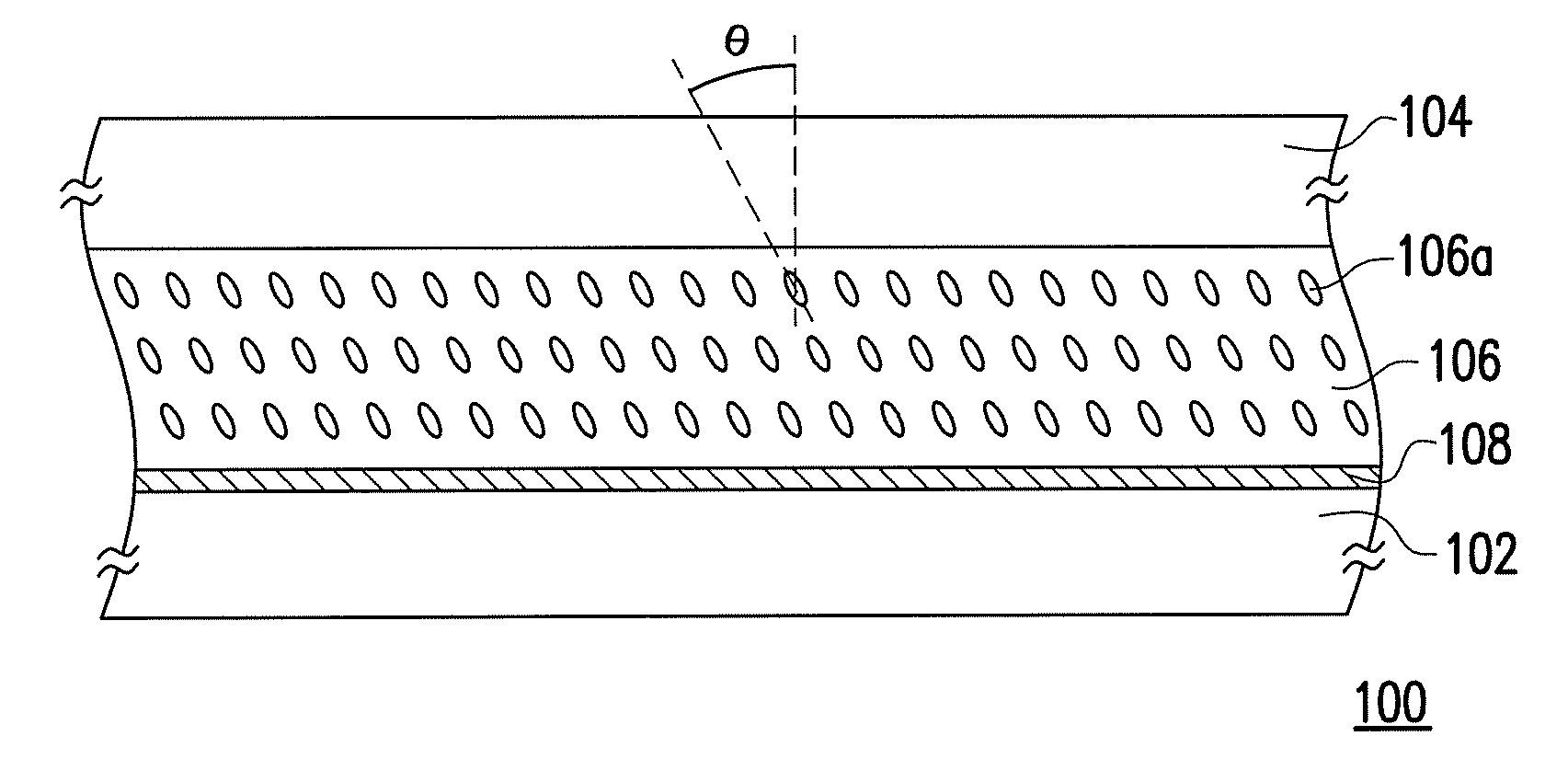
[0044]FIG. 2 is a schematic cross-sectional view of an LCD panel according to the first embodiment of the present invention. Referring to FIG. 2, an LCD panel 100 includes a first substrate 102, a second substrate 104, a liquid crystal layer 106 and a polymer stabilized alignment layer 108. The first substrate 102 is, for example, an active or passive switch device array substrate. The second substrate 104 is an opposite substrate disposed opposite to the first substrate 102, such as a color filter substrate. The liquid crystal layer 106 is disposed between the first substrate 102 and the second substrate 104. The liquid crystal layer 106 has a plurality of vertically-aligned liquid crystal molecules 106a. Due to the function of a polymer stabilized alignment layer 108, the liquid crystal molecules 106a are aligned at a pre-tilt angle θ.

[0045]According to the present embodiment of the present invention, the polymer stabilized alignment layer 108 is disposed between t...

Example

Second Embodiment

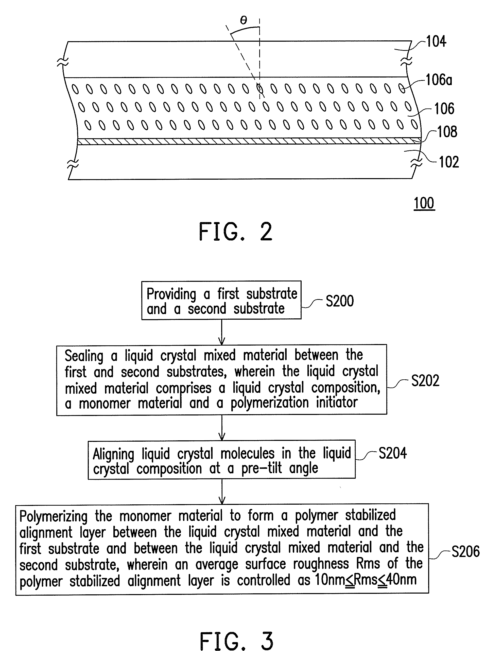
[0051]FIG. 3 is a flowchart of fabricating an LCD panel according to the second embodiment of the present invention. FIGS. 4A through 4D show schematic cross-sectional views of fabricating an LCD panel according to the second embodiment of the present invention.

[0052]Referring to both FIGS. 3 and 4A, first, a step S200 is performed to provide a first substrate 302 and a second substrate 304. The first substrate 302 is an active device array substrate, and the second substrate 304 is a color filter substrate, for example. The first substrate 302 includes a substrate (not shown) and an active layer (not shown). The second substrate 304 includes a substrate (not shown) and a color filter (not shown). In other embodiments, the first substrate may also be a color filter on array (COA) substrate which integrates the color filter on the active layer or an array on color filter (AOC) substrate which integrates the active layer on the color filter. Correspondingly, the secon...

Example

Third Embodiment

[0058]FIG. 5 is a schematic cross-sectional view of an LCD panel according to the third embodiment of the present invention. An LCD panel 300a has a structure similar to a structure of the LCD panel 300 in FIG. 4D, and thus the same components will be indicated with the same reference numerals. According to the present embodiment, in order to improve the aligning ability on the liquid crystal molecules, an alignment layer 316 and an alignment layer 318 are formed between the polymer stabilized alignment layer 312 and the first substrate 302 and between the polymer stabilized alignment layer 314 and the second substrate 304 respectively. In other words, in the flowchart of fabricating the LCD panel in the second embodiment, before sealing the liquid crystal mixed material 306, the alignment layers 316 and 318 are formed on the first substrate 302 and the second substrate 304 respectively. A material of the alignment layers 316 and 318 is, for example, polyimide or oth...


PUM

PropertyMeasurementUnit
Timeaaaaaaaaaa
Timeaaaaaaaaaa
Timeaaaaaaaaaa

Abstract

A liquid crystal display panel including a first substrate, a second substrate, a liquid crystal layer, and a polymer stabilized alignment layer is provided. The second substrate is disposed opposite to the first substrate. The liquid crystal layer is disposed between the first substrate and the second substrate. The polymer stabilized alignment layer is disposed between the first substrate and the liquid crystal layer, and an average surface roughness of the polymer stabilized alignment layer is greater than or equal to 10 nm.

Description

CROSS-REFERENCE TO RELATED APPLICATION[0001]This application claims the priority benefit of Taiwan application serial no. 97127656, filed on Jul. 21, 2008. The entirety of the above-mentioned patent application is hereby incorporated by reference herein and made a part of specification.BACKGROUND OF THE INVENTION[0002]1. Field of the Invention[0003]The present invention relates to a display panel and a fabricating method thereof, and more particularly to a liquid crystal display (LCD) panel and a fabricating method thereof.[0004]2. Description of Related Art[0005]Conventionally, the multi-domain vertically aligned liquid crystal display (MVA-LCD) panel utilizes an alignment structure to make liquid crystal molecules in different regions tilt at different angles to achieve the effect of wide viewing angle. The alignment structure includes alignment protrusions and alignment slits disposed on electrodes. However, light leakage usually occurs due to the disclination in tilt directions ...

Claims


Application Information

Patent Timeline
IPC IPC(8): G02F1/1337
CPCG02F2001/133715G02F2001/13415Y10T428/1005Y10T428/10G02F1/133788G02F1/133711G02F1/1337G02F2001/133765G02F2201/40G02F2001/133742G02F1/133715G02F1/133742G02F1/133765G02F1/13415C09K2323/00C09K2323/02
Inventor CHIANG, CHENG-JUNGCHIU, CHIH-HOHSIEH, CHUNG-CHINGPAI, CHIA-HSUANHUANG, BO-HSINCHEN, TE-SHENG
Owner AU OPTRONICS CORP
Why Eureka
Try Eureka