Filter Unit and Method for Generating Subband Filter Impulse Responses

a filter unit and impulse response technology, applied in the field of filter compressors, can solve the problems of increasing the computational complexity of the qmf domain representation and implementation of the filtering, the inability to reduce the overall computational complexity, and the inability to achieve significant computational complexity of the filtering of the four hrtf filters in the qmf domain. achieve the effect of simplifying the hrtf filter, reducing complexity, and realistic room effects

Active Publication Date: 2010-01-21
DOLBY INT AB
View PDF7 Cites 69 Cited by
  • Summary
  • Abstract
  • Description
  • Claims
  • Application Information

AI Technical Summary

Benefits of technology

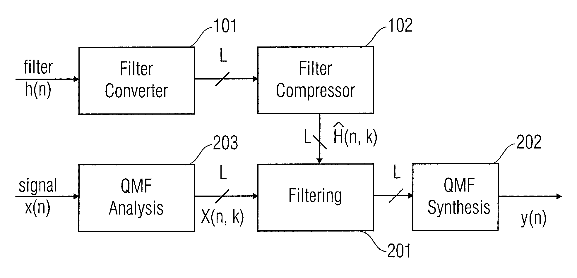
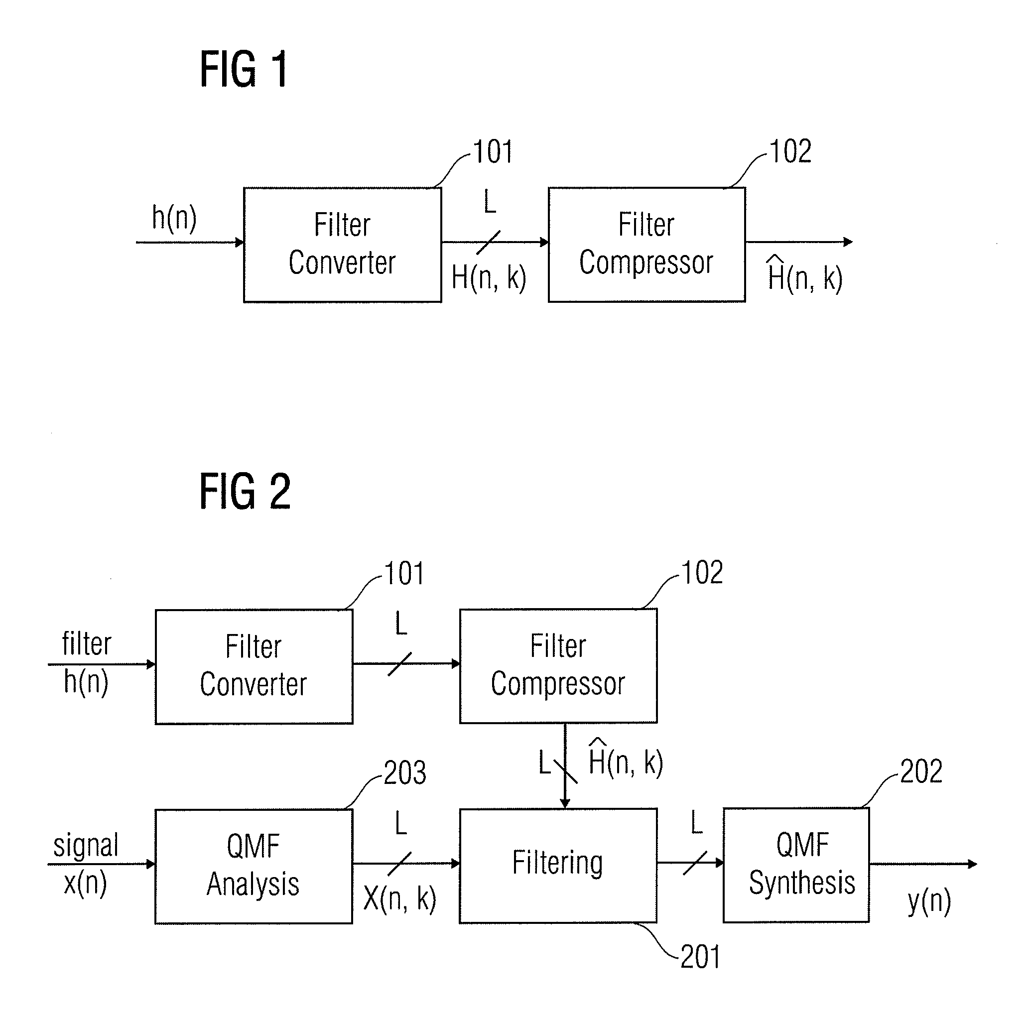
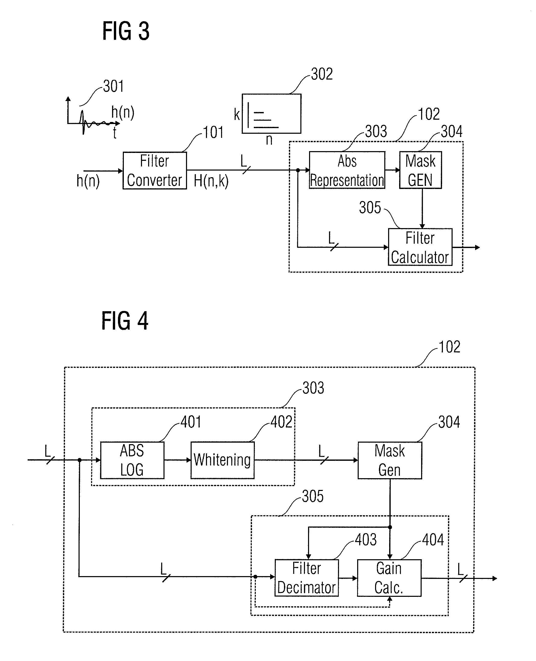
[0021]For instance, in the case of HRTF filters, after converting the time-domain HRTF filters to a complex QMF representation, some of the time-frequency tiles in the complex QMF representation can have low absolute values (at the aliasing level of the MPEG surround filterbank). These entries in the complex QMF representation of the HRTF filters may then be set to zero. This enables a complexity reduction for implementing long HRTF filters with room-response included in the complex QMF representation. Therefore, in order to achieve a binauralization at a reduced complexity, while maintaining realistic room effects, a filter converter may be followed by a filter reduction process in the form of an embodiment of a filter compressor. The filt...

Problems solved by technology

Even so, the computational complexity of the QMF domain representation and implementation of the filtering can be substantial, for instance in the case of filters having a long impulse response in the time-domain.
However, the HRTF filters can be quite long in order to nicely model room characteristics, and therefore the computational complexity of filtering the four HRTF filters in the Q...

Method used


Image

  • Filter Unit and Method for Generating Subband Filter Impulse Responses
  • Filter Unit and Method for Generating Subband Filter Impulse Responses
  • Filter Unit and Method for Generating Subband Filter Impulse Responses

Examples


Embodiment Construction

[0039]The below-described embodiments are merely illustrative for the principles of the present invention for an efficient filter representation. It is understood that modifications and variations of the arrangements and the details described herein will be apparent to others skilled in the art. It is the intent, therefore, to be limited only by the scope of the impending patent claims and not by the specific details presented by way of description and explanation of the embodiments herein.

[0040]Before describing the embodiment of the present invention in more detail, additional components and applications of embodiments, it should be noted that objects, structures and components with the same or similar functional properties are denoted with the same reference signs. Unless explicitly noted otherwise, the description with respect to objects, structures and components with similar or equal functional properties and features can be exchanged with respect to each other. Furthermore, i...


PUM


Abstract

A filter compressor for generating compressed subband filter impulse responses from input subband filter impulse responses corresponding to subbands, which include filter impulse response values at filter taps, includes a processor for examining the filter impulse response values from at least two input subband filter input responses to find filter impulse response values having higher values and at least one filter impulse response value having a value being lower than the higher values, and a filter impulse response constructor for constructing the compressed subband filter impulse responses using the filter impulse response values having the higher values, wherein the compressed subband filter impulse responses do not include filter impulse response values corresponding to filter taps of the at least one filter impulse response value having the lower value or include zero-valued values corresponding to filter taps of the at least one filter impulse response value having the lower value.

Description

CROSS-REFERENCE TO RELATED APPLICATIONS[0001]This application is a U.S. National Phase Entry of PCT / EP2007 / 005887 filed 3 Jul. 2007, which claims priority to Swedish Patent Application No. 0601462-5 filed 4 Jul. 2006 and U.S. Patent Application No. 60 / 806,607 filed 5 Jul. 2006.TECHNICAL FIELD[0002]The present invention relates to a filter compressor in the subband domain which is sometimes also referred to as the QMF domain (QMF=Quadrature Mirror Filterbank), which can for instance be employed in the field of audio applications such as filtering of head related transfer functions (HRTF) for a multi-channel sound experience over headphones.BACKGROUND OF THE INVENTION[0003]Recent development in filter conversion techniques has enabled a very efficient QMF representation of a time-domain filter. In general any FIR filter (FIR=Finite Impulse Response) in the time-domain can be converted into a set of complex filters each corresponding to a specific subband in the QMF. Hence, the filteri...

Claims


Application Information

Patent Timeline
IPC IPC(8): G10L19/00G10L19/14G10L19/02H04R5/00
CPCG10L19/0204H03H17/0272H03H17/0266H03H17/02H04S5/00G10L19/02H03M7/30
Inventor VILLEMOES, LARS
Owner DOLBY INT AB
Why Eureka
Try Eureka