
Beam For A Co-Ordinate Measuring Machine, Method For Its Production, and Measuring Machine Provided with Said Beam

Active Publication Date: 2010-01-28
HEXAGON METROLOGY SPA
View PDF9 Cites 20 Cited by
  • Summary
  • Abstract
  • Description
  • Claims
  • Application Information

AI Technical Summary

Benefits of technology

[0005]The aim of the present invention is to provide a beam for a measuring machine that will enable solution of the problems connected to the prior state of the art and discussed above.

Problems solved by technology

However, the dimensions of the cross section are such as not to enable use of conventional extrusion techniques.
The beam must thus be obtained by casting, which entails high production costs for a twofold reason.
In the first place, the process of casting in itself is more costly than extrusion; in the second place, the metallurgical properties of a rough beam obtained by means of casting are such as not to enable construction of the slide guides for the carriage directly on the rough beam via operations of machining (micromilling) and surface hardening.

Method used


Image

  • Beam For A Co-Ordinate Measuring Machine, Method For Its Production, and Measuring Machine Provided with Said Beam
  • Beam For A Co-Ordinate Measuring Machine, Method For Its Production, and Measuring Machine Provided with Said Beam
  • Beam For A Co-Ordinate Measuring Machine, Method For Its Production, and Measuring Machine Provided with Said Beam

Examples


Embodiment Construction

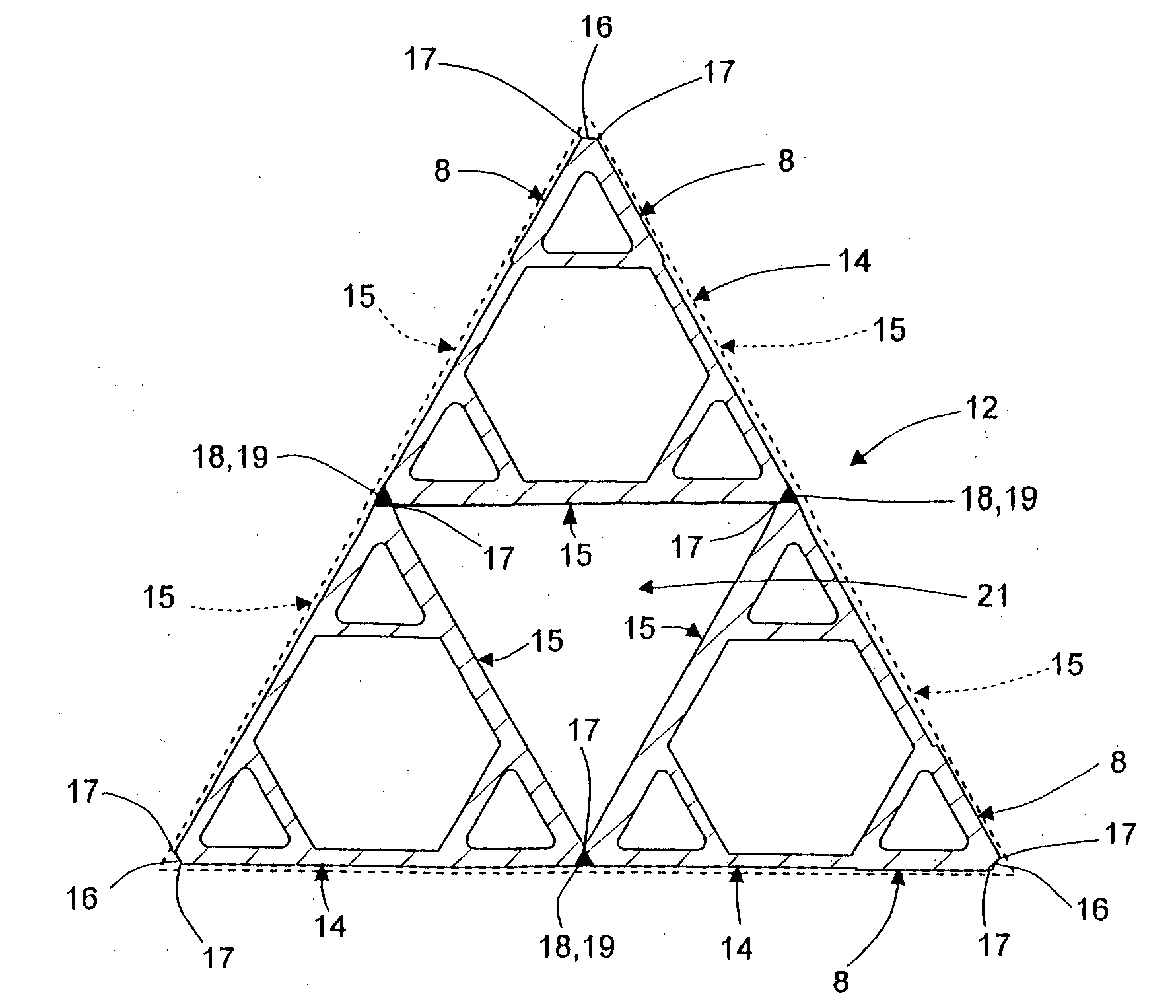
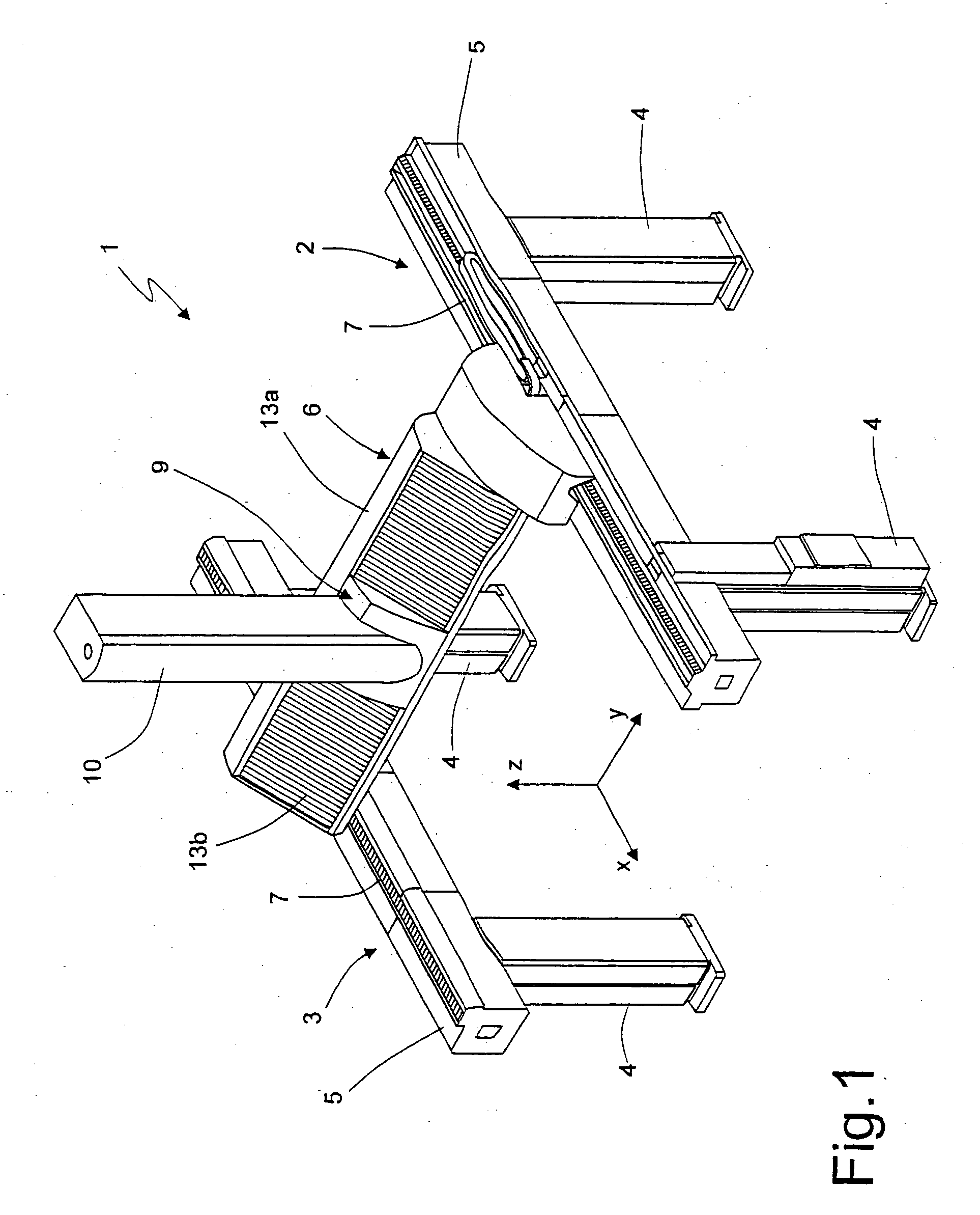
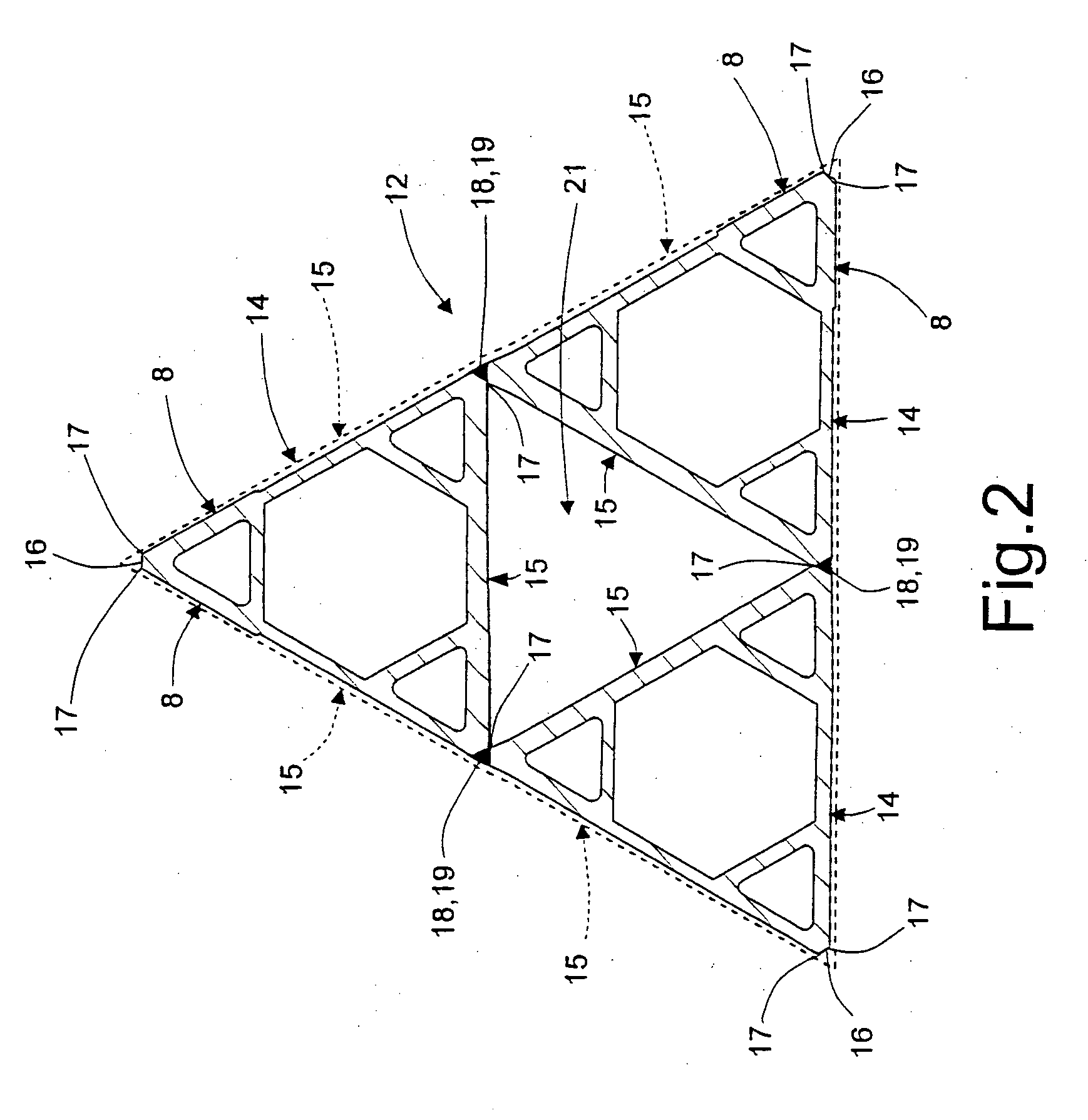
[0017]With reference to FIG. 1, designated by 1 is a pillar measuring machine comprising a pair of lateral supporting structures 2, 3, each constituted by a plurality of vertical pillars 4 aligned to one another (in the example illustrated, only two) and by a top horizontal fixed beam 5 supported by the pillars 4. The fixed beams 5 of the two supporting structures 2, 3 are parallel to one another and to a first co-ordinate axis X of the machine 1. The machine 1 moreover comprises a horizontal cross member 6 transverse to the fixed beams 5, which is supported thereby and can slide in the direction of the first axis X on guides 7 made on the fixed beams 5 themselves. The cross member 6 comprises a mobile beam 12, hereinafter defined simply as “beam 12”, illustrated in sectional view in FIG. 2 but not visible clearly in FIG. 1 in so far as it is provided with guards 13a, 13b of a conventional type. The beam 12 in turn defines a plurality of guides 8 (FIG. 2) parallel to a longitudinal ...


PUM

PropertyMeasurementUnit
Widthaaaaaaaaaa

Abstract

A beam for a measuring machine is constituted by a plurality of extruded beam elements, which are set alongside one another and welded together so that each forms a portion of the cross section of the beam itself; the beam elements and the beam have a hollow section shaped like an equilateral triangle.

Description

TECHNICAL FIELD[0001]The present invention relates to a beam for a co-ordinate measuring machine, as well as to a method for its production and to a measuring machine provided with said beam.[0002]The present invention finds a particularly advantageous, albeit not exclusive, application in co-ordinate measuring machines of large dimensions of the type with pillars, to which reference will be made in what follows by way of example, for greater clarity, without this implying any loss of generality.BACKGROUND ART[0003]Known to the art are pillar measuring machines comprising a pair of lateral supporting structures, each constituted by a plurality of vertical pillars aligned with respect to one another and by a top horizontal fixed beam supported by the pillars. The fixed beams of the two supporting structures are parallel to one another and to a first co-ordinate axis of the machine. The machine moreover comprises a mobile beam, horizontal and transverse to the fixed beams, which is su...

Claims


Application Information

Patent Timeline
IPC IPC(8): E04C3/00B23K31/02
CPCE04C3/06E04C2003/0413G01B5/008E04C2003/0469E04C2003/043
Inventor GARAU, ENRICO
Owner HEXAGON METROLOGY SPA
Features
  • Generate Ideas
  • Intellectual Property
  • Life Sciences
  • Materials
  • Tech Scout
  • Unparalleled Data Quality
  • Higher Quality Content
  • 60% Fewer Hallucinations
Learn More