Electromotive liquid handling method and apparatus

a liquid handling and electromagnet technology, applied in the direction of fluid pressure measurement, liquid/fluent solid measurement, peptide measurement, etc., can solve the problems of local heating gradients of conductivity and permittivity, lack of efficient multi-purpose device, and more difficult to manipulate fluids, etc., to achieve efficient fluid manipulation

Inactive Publication Date: 2010-01-28
RGT UNIV OF CALIFORNIA
View PDF4 Cites 2 Cited by
  • Summary
  • Abstract
  • Description
  • Claims
  • Application Information

AI Technical Summary

Benefits of technology

[0019]A device containing electrodes capable of inducing electrokinetic (including electroosmotic and electrothermal) fluid flow inside vessels (including microplates or well-plates). The device is either applied externally by inserting electrodes inside the vessel, or the device is built into the vessel, itself, if flow is generated by forces other than single-frequency electroosmosis. The device can be used for general manipulation of fluids and particles inside the vessel, including concentration, separation, transport, mixing or cell electroporation. The device is tunable, so that by applying different DC and / or AC voltages, different flow effects can be induced and adapted to efficiently manipulate the fluids and particles contained inside the vessel. The device can perform one or more particle manipulation operations.

Problems solved by technology

Furthermore, local heating creates gradients of conductivity and permittivity.
Massively parallel hybridization [1]-13] improves the way many biological and medical analyses are performed both in research and clinical applications, but there is still a lack of an efficient multipurpose device.
As sample volumes used in massive parallel systems become smaller and smaller (micro- to nanoliter or even smaller) it is more challenging to manipulate the fluids since the fluid viscosity dominates any convection.

Method used


Image

  • Electromotive liquid handling method and apparatus
  • Electromotive liquid handling method and apparatus
  • Electromotive liquid handling method and apparatus

Examples


Embodiment Construction

[0025]In the following description of the preferred embodiment, reference is made to the accompanying drawings which form a part hereof, and in which is shown by way of illustration a specific embodiment in which the invention may be practiced. It is to be understood that other embodiments may be utilized and structural changes may be made without departing from the scope of the present invention.

[0026]Overview

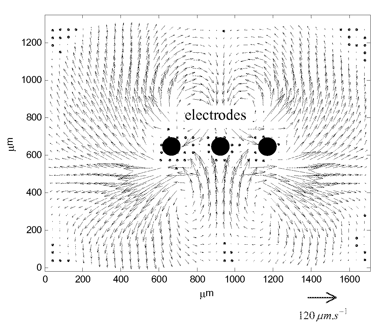
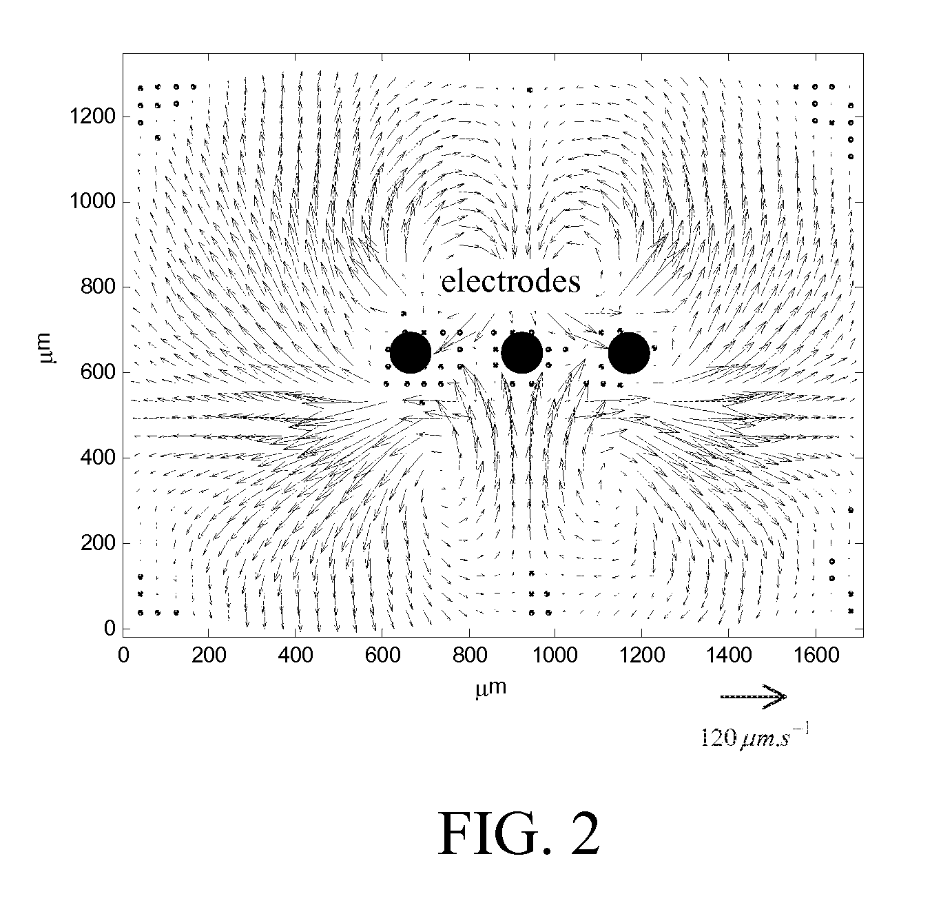
[0027]The impact of the manipulation of fluids and / or particles induced by electric fields is described theoretically and experimentally herein. By means of a microfluidic device comprising a periodic array of microelectrodes, fluid(s) and / or particles manipulations are shown including concentration, separation, transport or mixing using electrokinetic properties. The theoretically predicted dynamical phenomena are demonstrated experimentally.

[0028]This invention could be used, for example, to improve the mixing of microliter or nanoliter volume protein solutions analyzed in h...


PUM

PropertyMeasurementUnit
electric fieldsaaaaaaaaaa
shapeaaaaaaaaaa
flexibleaaaaaaaaaa

Abstract

An apparatus and method to achieve manipulation of particles and/or solutions through the induction of electromagnetic fields inside liquid contained inside vessels are disclosed. A “vessel” denotes specifically either a microtitter plate (microplate or well-plate, 1536, 3456 or any other format) well or hybridization solution placed on microarrays for hybridization experiment purposes or more generally any volume containing liquid solution. The manipulation is performed by bringing the active part of the device into contact with the fluidic solution, wherein electromagnetic fields and/or induced fluid flow are used to perform specific manipulations including transport, separation, concentration, mixing, reaction and electroporation. The invention can be used to enhance processing in a number of standard assays and protocols, including the Polymerase Chain Reaction, kinase-based assays, ELISA assays and electroporation.

Description

CROSS-REFERENCE TO RELATED APPLICATION[0001]This application claims the benefit under 35 U.S.C. Section 119(e) of the following co-pending and commonly-assigned U.S. patent application:[0002]U.S. Provisional Application Ser. No. 60 / 908,112, filed on Mar. 26, 2007, by Igor Mezic and Frederic Bottausci, entitled “ELECTROMOTIVE LIQUID HANDLING METHOD, APPARATUS, AND PROCESS,” attorneys' docket number 30794.224-US-P1 (2007-425-1);[0003]which application is incorporated by reference herein.STATEMENT REGARDING FEDERALLY SPONSORED RESEARCH AND DEVELOPMENT[0004]This invention was made with Government support under Grant No. DMS-0507256 awarded by the NSF. The Government has certain rights in this invention.BACKGROUND OF THE INVENTION[0005]1. Field of the Invention[0006]The present invention relates in general to the field of manipulating fluid flow and / or particle motivating force and is related to separation, concentration, transport, dispersion, reaction and mixing apparatus, method and p...

Claims


Application Information

Patent Timeline
Patent Type & Authority Applications(United States)
IPC IPC(8): C07K1/26G01N27/26
CPCB01L3/5025B01L7/52B01L2300/0829G01N2035/00534B01L2400/0418G01N35/00B01L2400/0415
Inventor MEZIC, IGORBOTTAUSCI, FREDERIC
Owner RGT UNIV OF CALIFORNIA
Why Eureka
Try Eureka