Unwinding device for reels of web material with dual drive mechanism and relative unwinding method

a technology of unwinding device and reel, which is applied in the direction of thin material handling, function indicators, filament handling, etc., can solve the problems of loss of properties, permanent deformation, and low winding density of reels, and achieve the effect of little winding density

Inactive Publication Date: 2008-12-02
FABIO PERINI SPA
View PDF25 Cites 14 Cited by
  • Summary
  • Abstract
  • Description
  • Claims
  • Application Information

AI Technical Summary

Benefits of technology

[0010]The object of the present invention is to produce an unwinding device for unwinding reels of web material which may efficiently also manipulate reels with large diameters and / or reels with very little winding density and / or of soft and delicate material and which is particularly suitable for manipulating reels of tissue paper.
[0011]Another object of the present invention is to produce an unwinding device which can unwind reels of web material without the risk of reciprocal slippage between the, turns of web material and of damage to the material.

Problems solved by technology

In certain particular situations, such as when the reel of web material is exceptionally large in size and / or has a limited winding density, peripheral drawing is not suitable, as it may cause phenomena of reciprocal slippage between the turns of material wound on the reel (especially in the central zone of the reel), as a result of poor adhesion of the turns of web material and / or of the high inertia of the reel and its central shaft.
Difficulties in unwinding occur in particular when the dimensions of the reel are considerable and the web material wound is particularly soft and delicate, such that when it is wound on the reel it cannot be tightened and the reel thus has a low winding density.
This is not advisable as it would cause permanent deformation of the web material with loss of those properties of softness and bulk obtained during production of the material using special procedures.
These systems with central operation are not satisfactory, especially when the reel has a large diameter and high inertia.
When this occurs the web material often breaks due to the fact that the edge of the outermost turn of the material is pinched and withheld between the flat frontal surface of the reel and the relative rotating plate mechanism.

Method used


Image

  • Unwinding device for reels of web material with dual drive mechanism and relative unwinding method
  • Unwinding device for reels of web material with dual drive mechanism and relative unwinding method
  • Unwinding device for reels of web material with dual drive mechanism and relative unwinding method

Examples


Embodiment Construction

[0047]The invention is described below applied to an unwinding device comprising a dual carriage for simultaneously supporting two reels, one of which in stand-by and the other being unwound. This type of unwinding device is used to change the used up reel in automatic mode. It must however be understood that the underlying principles of the invention may also be applied to an unwinding device of another type.

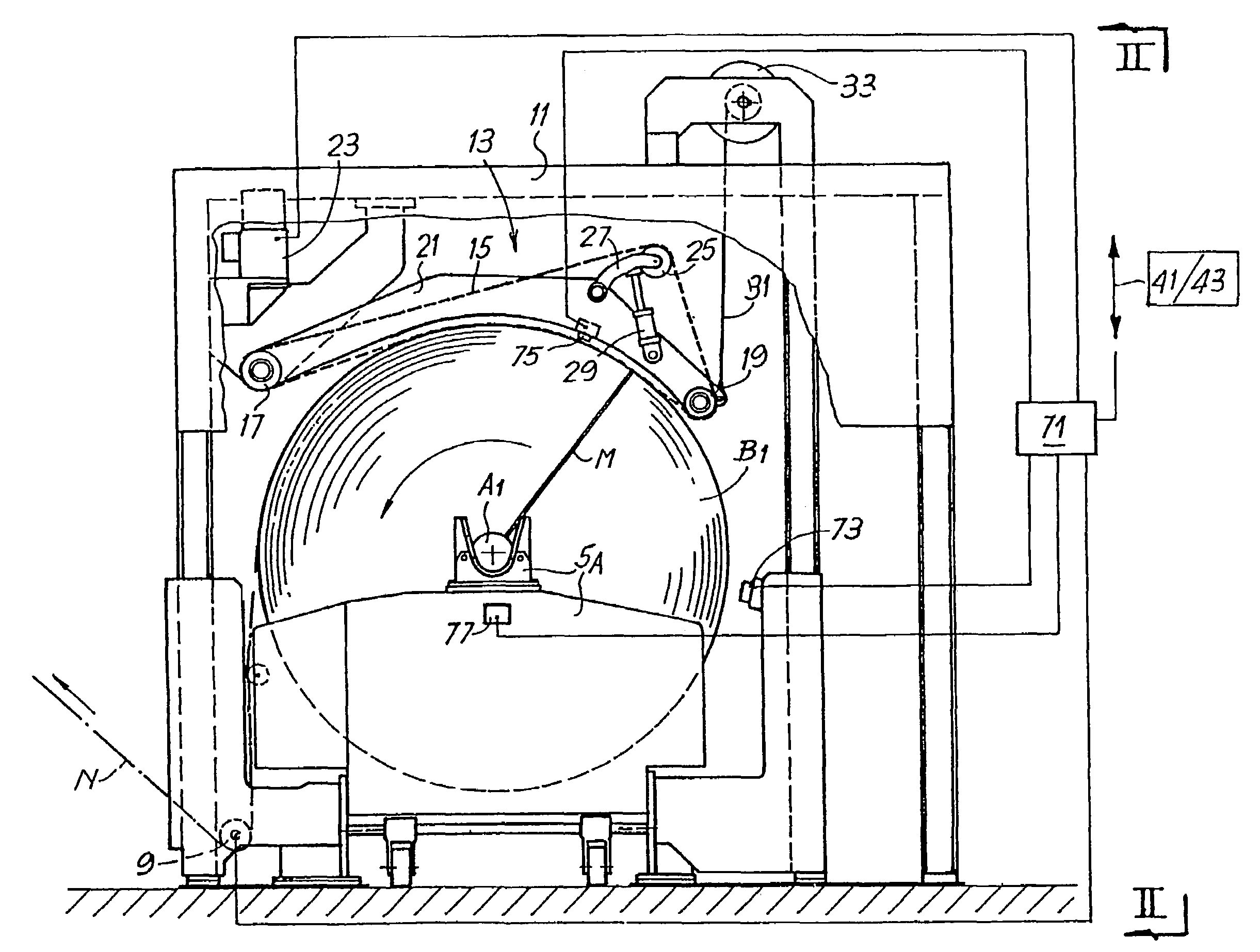
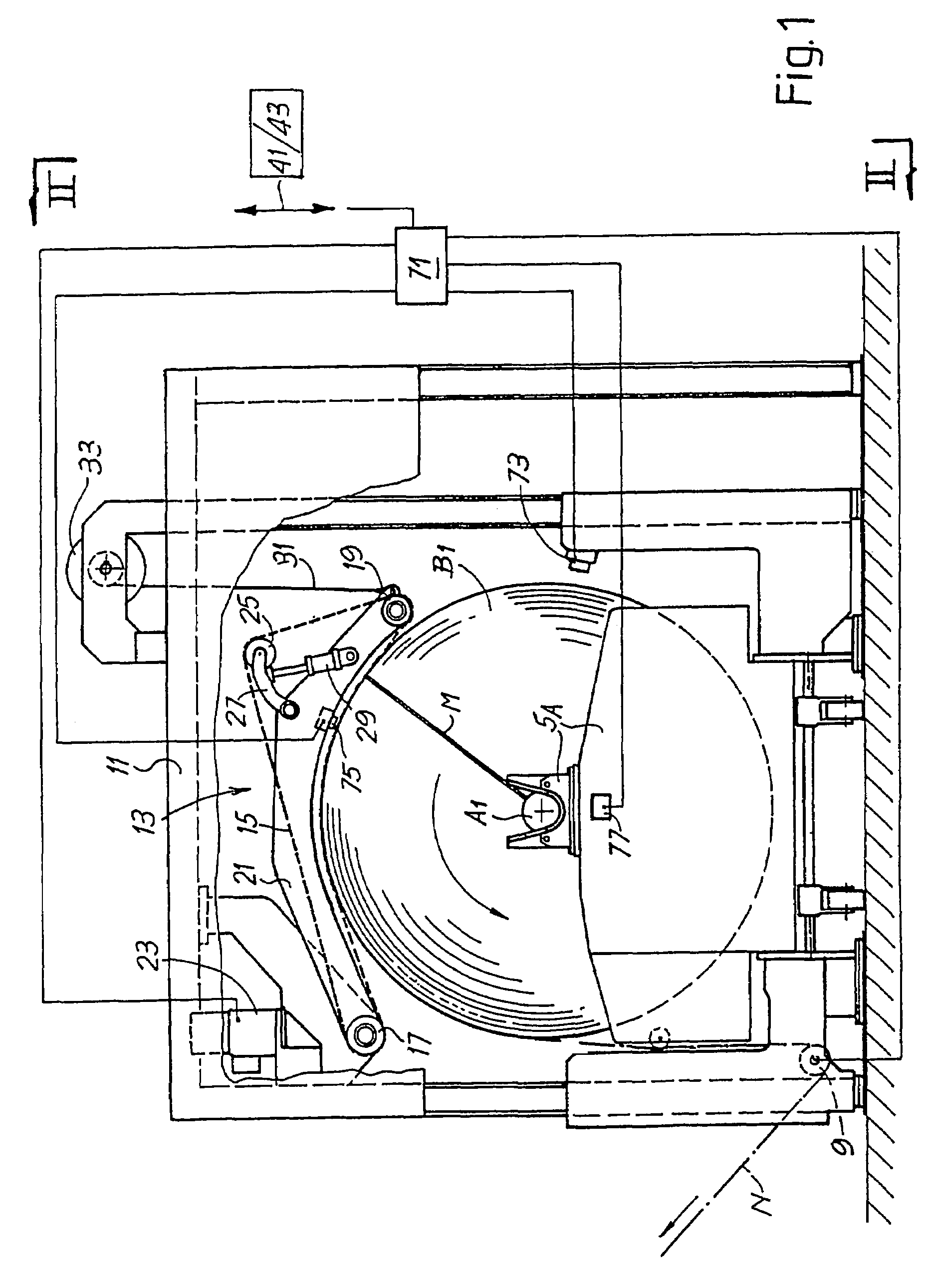
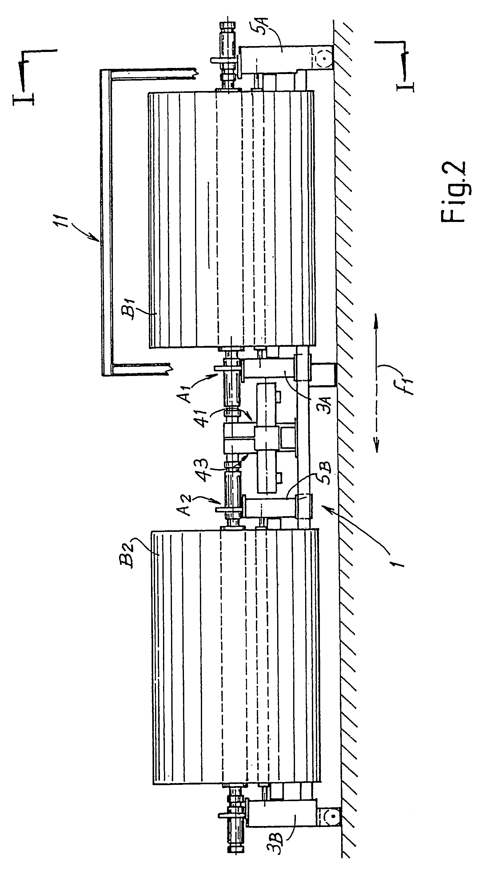
[0048]The overall structure of the unwinding device incorporating the present invention is shown in FIGS. 1 and 2. In this embodiment the unwinding device comprises a dual carriage 1 that moves according to the double arrow f1 (FIG. 2), provided with two pairs of side supports 3A, 5A and 3B, 5B to simultaneously support two reels B1 and B2. Each of the two reels B1, B2 is wound on a central shaft or core, indicated with A1 and A2 for the two reels B1 and B2 respectively.

[0049]The reel B1 is in an unwinding position, corresponding to a processing line to which the web material N...


PUM

PropertyMeasurementUnit
torqueaaaaaaaaaa
angular displacementaaaaaaaaaa
speedaaaaaaaaaa

Abstract

The device comprises: supports (3A, 5A; 3B, 5B) to support at least a reel (B1) in an unwinding position; at least a peripheral drive mechanism which acts on the cylindrical surface of the reel being unwound and transmits peripherally to said reel a torque to draw it in rotation; and at least a center drive mechanism (41) which transmits centrally to said reel an auxiliary torque to draw it in rotation together with the torque transmitted by the peripheral drive mechanism.

Description

TECHNICAL FIELD[0001]The present invention relates to an unwinding device to unwind reels or rolls of web material and feed the web material to subsequent stations of a converting line or similar. More particularly, although not exclusively, the present invention relates to a device of the aforesaid type for unwinding reels of paper material, such as tissue paper to produce toilet paper, kitchen towels or similar, or napkins, handkerchiefs or other products.[0002]The present invention also relates to a method for unwinding a web material from a reel and delivering it to a converting line downstream.STATE OF THE ART[0003]In many industrial fields, in particular in the paper converting field, it is necessary to deliver a web material, for example a sheet of paper, from a starting reel or roll to a converting line in which the web material is manipulated to produce semi-finished or finished products. For example, to produce paper in rolls, such as toilet or kitchen paper, large reels a...

Claims


Application Information

Patent Timeline
Patent Type & Authority Patents(United States)
IPC IPC(8): B65H23/06B65H16/10
CPCB65H16/10B65H16/103B65H16/106B65H2301/41468B65H2403/72B65H2511/142B65H2513/10B65H2513/11B65H2515/31B65H2220/01B65H2220/02B65H2511/14
Inventor BETTI, GIULIOMORELLI, ROBERTOBENVENUTI, ANGELO
Owner FABIO PERINI SPA
Why Eureka
Try Eureka