Method for making twisted carbon nanotube wire

a carbon nanotube and wire technology, applied in the field of carbon nanotube structure making methods, can solve the problems of carbon nanotube arrays providing relatively weak pulling force, carbon nanotube applications, and difficult processing

Active Publication Date: 2014-03-11
TSINGHUA UNIV +1
View PDF14 Cites 20 Cited by
  • Summary
  • Abstract
  • Description
  • Claims
  • Application Information

AI Technical Summary

Benefits of technology

[0008]However, in the drawing and twisting process, the twisted carbon nanotube wire is joined with the carbon nanotube array, such that the carbon nanotube array can provide relatively weak pulling force (i.e., the van der Waals attractive force between adjacent carbon nanotubes). Therefore, the achieved twisted carbon nanotube wire may have clearances between adjacent carbon nanotubes due to the curve of the carbon nanotubes formed, and the density and tensile strength of the twisted carbon nanotube wire are relatively small.

Problems solved by technology

However, the main obstacle to actual application of carbon nanotubes is their difficulty to process due to the powder form of the carbon nanotube products.
However, in the drawing and twisting process, the twisted carbon nanotube wire is joined with the carbon nanotube array, such that the carbon nanotube array can provide relatively weak pulling force (i.e., the van der Waals attractive force between adjacent carbon nanotubes).

Method used


Image

  • Method for making twisted carbon nanotube wire
  • Method for making twisted carbon nanotube wire
  • Method for making twisted carbon nanotube wire

Examples


first embodiment

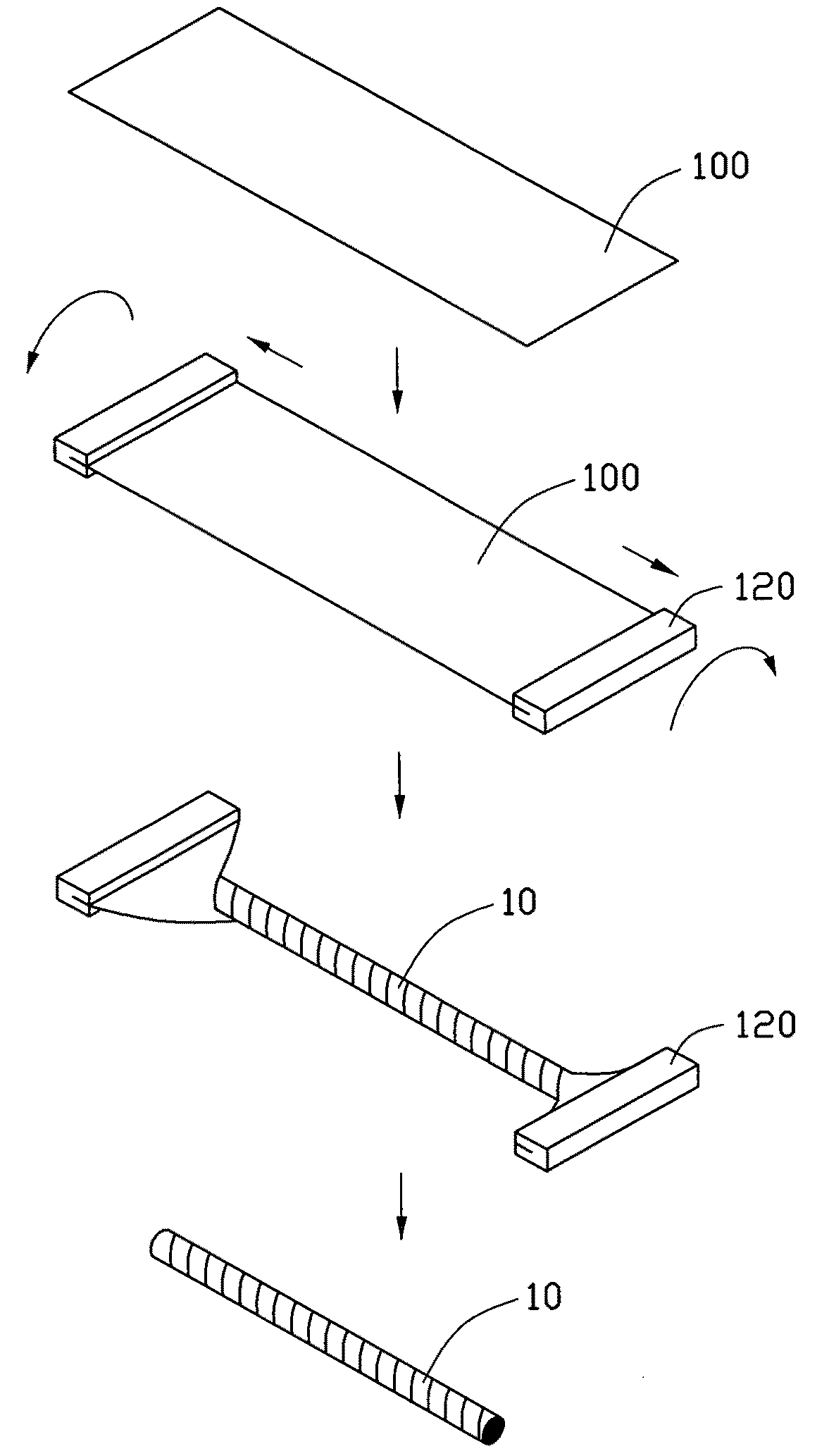
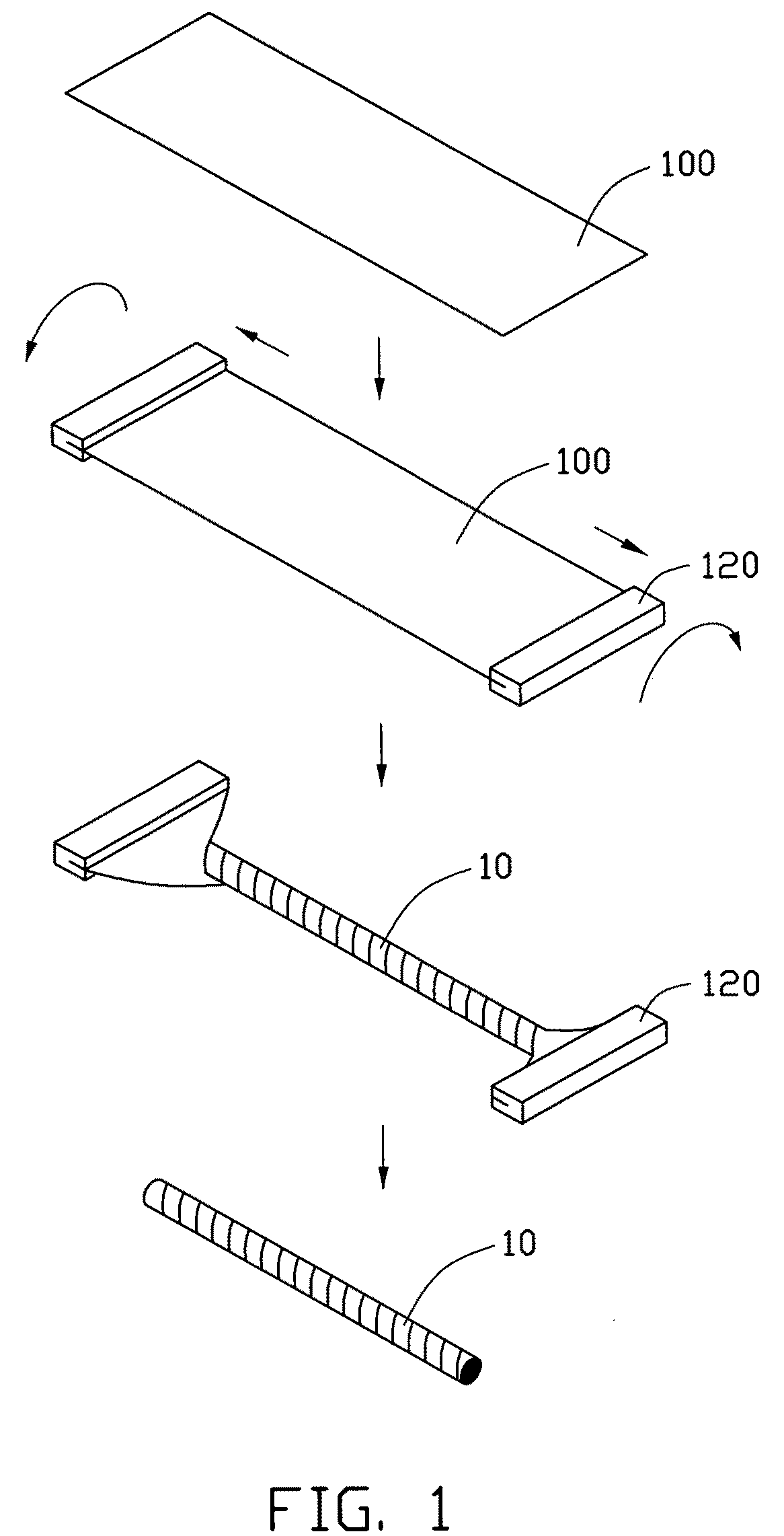
[0021]Referring to FIG. 1, a method for making a twisted carbon nanotube wire 10 includes steps of:[0022]S11 providing at least one carbon nanotube film 100 and two fixing elements 120;[0023]S12 clamping the carbon nanotube film 100 by the two fixing elements 120 at two opposite ends of the carbon nanotube film 100 along a length direction of the carbon nanotube film 100;[0024]S13 applying two different direction pulling forces on the two fixing elements 120 to draw the carbon nanotube film 100 along the length direction of the carbon nanotube film 100; and[0025]S14 rotating the two fixing elements 120, thereby twisting the carbon nanotube film 100 while the carbon nanotube film 100 is in a stretched state.

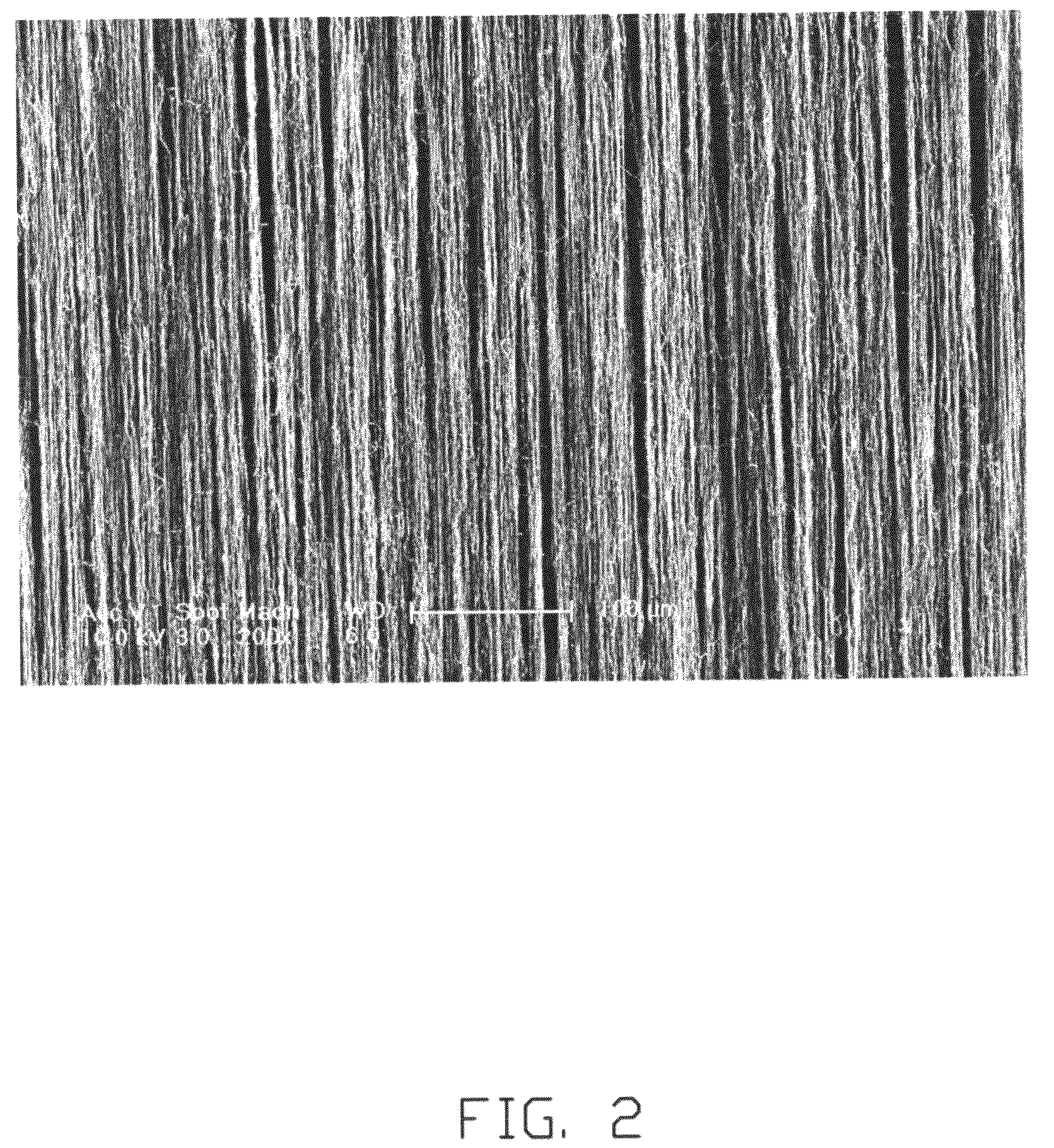
[0026]In step S11, the carbon nanotube film 100 includes a plurality of carbon nanotubes uniformly distributed therein, and aligned substantially along a length direction of the carbon nanotube film 100. Referring also to FIG. 2, more specifically, the carbon nanotube film 100 in...

second embodiment

[0042]Referring to FIG. 4, a method for making a twisted carbon nanotube wire 20 includes steps of:[0043]S21 providing at least one carbon nanotube array 210, and drawing / pulling a carbon nanotube film 230 from the at least one carbon nanotube array 210 by using a drawing tool 220;[0044]S22 contacting and supporting the carbon nanotube film 230 by at least one support cylinder 240;[0045]S23 pulling the drawing tool 220 thereby applying two pulling forces on the carbon nanotube film 230 along the direction of the carbon nanotube film 230; and[0046]S24 rotating the drawing tool 220, thereby twisting the carbon nanotube film 230 while the carbon nanotube film 230 is at a stretched state.

[0047]The step S21 is similar to the step S11, however, the carbon nanotube film 230 is still in the drawing period and joined with the carbon nanotube array 210. In the length direction, one end of the carbon nanotube film 230 is connected with the carbon nanotube array 210 by van der Waals attractive...

third embodiment

[0060]Referring to FIG. 7, a method for making a twisted carbon nanotube wire 30 includes steps of:[0061]S31 providing at least one carbon nanotube array 310, and drawing / pulling a carbon nanotube film 330 from the at least one carbon nanotube array 310 by using a drawing tool 320;[0062]S32 pressing the carbon nanotube film 330 by at least one pressing member 340;[0063]S33 pulling the drawing tool 320 thereby applying two different direction pulling forces on the carbon nanotube film 330 along the direction of the carbon nanotube film 330; and[0064]S34 rotating the drawing tool 320 thereby twisting the carbon nanotube film 330 while the carbon nanotube film 330 is at a stretched state.

[0065]The step S31 can be the same as the step of S21.

[0066]In step S32, the pressing member 340 sandwiches the carbon nanotube film 330 and applies a pressure and friction to the carbon nanotube film 330 as it travels through the pressing member 340. The pressing member 340 can press the carbon nanot...


PUM

PropertyMeasurementUnit
diameteraaaaaaaaaa
thicknessaaaaaaaaaa
specific surface areaaaaaaaaaaa

Abstract

The present invention relates to a method for making a twisted carbon nanotube wire. Two opposite ends of the at least one carbon nanotube film is clamped by two clamps. The two clamps is pulled along two reversed directions to stretch the at least one carbon nanotube film. The at least one carbon nanotube film is twisted by rotating the two clamps while the at least one carbon nanotube film is in a straightening state.

Description

CROSS-REFERENCE TO RELATED APPLICATIONS[0001]This application claims all benefits accruing under 35 U.S.C. §119 from Chinese Patent Application No. 200910109047.0, filed on Jul. 21, 2009, in the Chinese Intellectual Property Office, the contents of which are hereby incorporated by reference.BACKGROUND[0002]1. Technical Field[0003]The present disclosure relates to methods for making the carbon nanotube structures, particularly, to a method for making the twisted carbon nanotube wire.[0004]2. Description of Related Art[0005]Carbon nanotubes are tubules of carbon generally having a diameter of 0.5 to 100 nanometers, and composed of a number of coaxial cylinders of graphite sheets. Carbon nanotubes have interesting and potentially useful thermal, electrical and mechanical properties, and have recently attracted a great deal of attention for use in different applications such as field emitters, gas storage and separation, chemical sensors, and high strength composites.[0006]However, the ...

Claims


Application Information

Patent Timeline
Patent Type & Authority Patents(United States)
IPC IPC(8): D01F9/12
CPCB82Y40/00B82Y30/00C01B31/0253B82B3/00C01B32/168
Inventor LIU, KAIZHOU, RUI-FENGSUN, YING-HUIJIANG, KAI-LILIU, LIANGFAN, SHOU-SHAN
Owner TSINGHUA UNIV
Why Eureka
Try Eureka