Display module and driving method thereof
a technology of display module and driving method, which is applied in the direction of instruments, computing, chemistry apparatus and processes, etc., can solve the problem that the current display device tends to be lighter, and achieve the effect of reducing the number of driving elements, saving space, and reducing production costs
- Summary
- Abstract
- Description
- Claims
- Application Information
AI Technical Summary
Benefits of technology
Problems solved by technology
Method used
Image

Examples
first embodiment
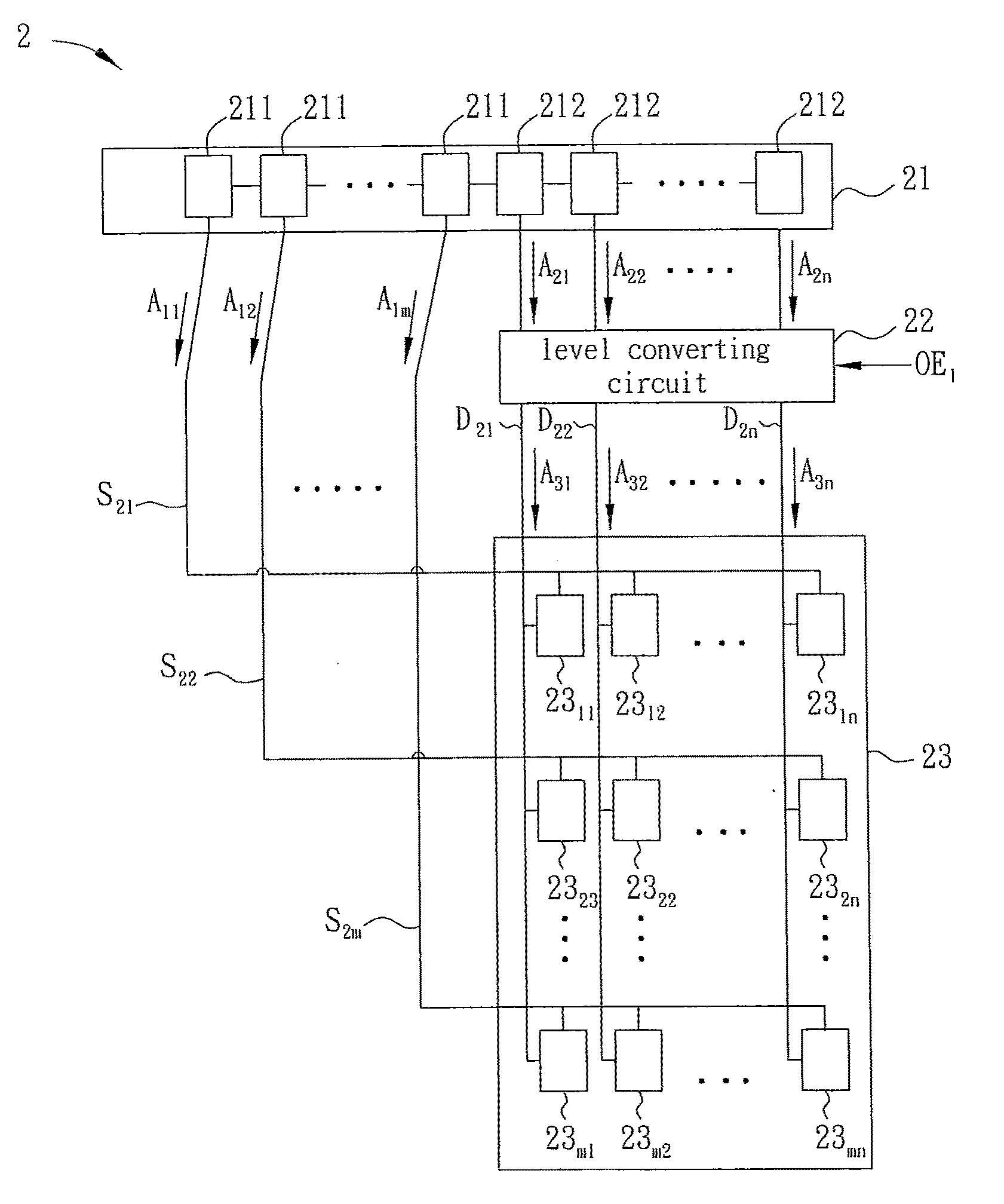
[0037]FIG. 4 is a schematic view of a display module 2. With reference to FIG. 4, the display module 2 includes a scan line, a data line, a driving circuit21, and a level converting circuit 22. In the embodiment, the display module 2 includes a plurality of scan lines S21˜S2m and a plurality of data lines D21˜D2n for example. The driving circuit 21 is electrically connected to the scan lines S21˜S2m and the level converting circuit 22 that is electrically connected to the data lines D21˜D2n, where m and n are positive integers greater than 1.
[0038]The driving circuit 21 includes at least one first driving unit and at least one second driving unit. In the embodiment, the driving circuit 21 has a plurality of first driving units 211 and a plurality of second driving units 212 for example. The first driving unit 211 is electrically connected to the second driving unit 212. Each of the first driving units 211 and second driving units 212 may have, for example but not limited to, the sam...
second embodiment
[0055]FIG. 11 is a schematic view of a display device 3. With reference to FIG. 11, the display module 3 includes a scan line, a data line, a driving circuit 31, and a level converting circuit 32. In the embodiment, the display module 3 includes a plurality of scan lines S21˜S2m and a plurality of data lines D21˜D2n for example. The driving circuit 31 is electrically connected to the data lines D21˜D2n and the level converting circuit 32, respectively. The level converting circuit 32 is electrically connected to the data lines S21˜S2m.
[0056]The driving circuit 31 has at least one first driving unit and at least one second driving unit. In the embodiment, the driving circuit 31 includes a plurality of first driving units 311 and a plurality of second driving units 312 for example. The first driving units 311 are electrically connected to the second driving units 312. Each of the first and second driving units 311 and 312 may have the same or different circuit structures, respectively...
third embodiment
[0063]FIG. 13 is a schematic view of a display device 4. With reference to FIG. 13, the display module 4 includes a scan line, a data line, a driving circuit 41, and a level converting circuit 42. In the embodiment, the display module 4 includes a plurality of scan lines S21˜S2m and a plurality of data lines D21˜D2n for example. The driving circuit 41 is electrically connected to the level converting circuit 42, which is electrically connected to the data lines D21˜D2n and scan lines S21˜S2m.
[0064]The driving circuit 41 includes at least one first driving unit and at least one second driving unit. In the embodiment, the driving circuit 41 has a plurality of first driving units 411 and a plurality of second driving units 412 for example. The first driving unit 411 is electrically connected to the second driving unit 412. Each of the first and second driving units 411 and 412 may have the same or different circuit structures and this is not limited herein.
[0065]As shown in FIG. 13, th...
PUM
 Abstract
Description
Claims
Application Information
 - R&D
- Intellectual Property
- Life Sciences
- Materials
- Tech Scout
- Unparalleled Data Quality
- Higher Quality Content
- 60% Fewer Hallucinations
Browse by: Latest US Patents, China's latest patents, Technical Efficacy Thesaurus, Application Domain, Technology Topic, Popular Technical Reports.
© 2025 PatSnap. All rights reserved.Legal|Privacy policy|Modern Slavery Act Transparency Statement|Sitemap|About US| Contact US: help@patsnap.com