Golf club velocity enhancement

a golf club and velocity technology, applied in the field of golf clubs, to achieve the effect of reducing air resistance to the movement accelerating the speed of the club head, and reducing the air pressur

Inactive Publication Date: 2010-01-28
DORAN DANIEL J
View PDF24 Cites 18 Cited by
  • Summary
  • Abstract
  • Description
  • Claims
  • Application Information

AI Technical Summary

Benefits of technology

[0006]The invention involves a golf club head having one or more air passages extending from the front face of the club head to the trailing face of the club head, so that during a ball-striking event some of the air in front of the club head is transferred through the passage(s) to the wake area behind the club head. This transfer of

Problems solved by technology

One obstacle to a higher club head velocity is the air resistance or turbulence associated with arcuate travel of the club head from the starting (elevated) position to the b

Method used


Image

  • Golf club velocity enhancement
  • Golf club velocity enhancement
  • Golf club velocity enhancement

Examples


Embodiment Construction

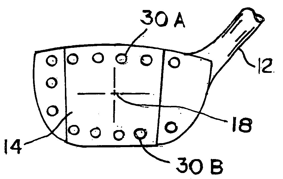
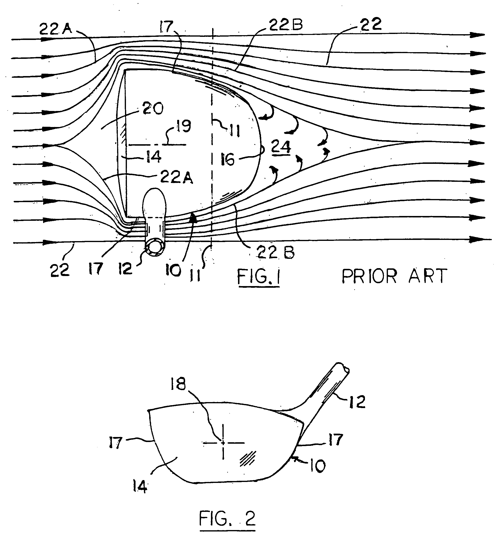
[0015]Before describing the golf club of the present invention, it is believed that a better understanding of the invention can be realized by first describing the conventional prior art golf club, as shown, e.g., in FIGS. 1 and 2. The conventional golf club comprises a club head 10 attached to a conventional shaft 12. The club head has a ball-striker front face 14, a convex curvilinear rear face 16, and side surfaces 17 extending rearwardly from the peripheral edges of front face 14 to merge smoothly with curvilinear rear face 16. As shown in FIG. 1, side surfaces 17 taper in a direction from the front face to the rear face, so as to promote (as much as possible) a smooth air flow relative to the club head. The flow is “relative” since the club head is moving in a right-to-left direction, while the air is essentially stagnant except for air that is momentarily displaced by passage of the club head. Numeral 22 generally designates the relative air stream components, particularly the...


PUM


Abstract

A golf club includes a club head that has one or more air passages extending from its front face to its rear face, so that when the club is swung in a ball-striking action air in the path of the club head is transferred from a pressurized zone on the head front face through the air passages into a low pressure wake area behind the club head. The air transfer action minimizes resistance to club movement, so as to contribute to a faster club head speed and a longer ball travel.

Description

FIELD OF INVENTION[0001]This Invention relates to golf clubs and particularly to an improved golf club head that will enable the golfer to swing the golf club so that the club head has a greater velocity (as compared with the velocity of a generally similar conventional golf club). The present invention relates to club head velocity enhancement.DESCRIPTION OF THE RELATED ART[0002]FIGS. 1 and 2 of the attached drawings show a golf club having a club head of generally conventional construction (or shape). During a golf ball-striking event the club head is swung in an arc from a starting position in which the club head is above and slightly behind the golfer's head. The club head travels in an arc angularly downwardly and then in front of the golfer's upright body so as to come into forcible contact with a stationary golf ball located at or slightly above ground level.[0003]The club head continues the arcuate movement to an elevated point away from the golfer's body, while the golf bal...

Claims


Application Information

Patent Timeline
IPC IPC(8): A63B53/04
CPCA63B49/06A63B53/0466A63B2053/0416A63B2059/0011A63B2225/01A63B59/0088A63B60/50A63B60/52A63B53/0416A63B60/006
Inventor DORAN, DANIEL J.
Owner DORAN DANIEL J
Why Eureka
Try Eureka