Eureka AIR delivers breakthrough ideas for toughest innovation challenges, trusted by R&D personnel around the world.

Fly-by-wire flight control system with electronic lead/lag damper algorithm

a flight control system and electronic technology, applied in the direction of wind motors with perpendicular air flow, navigation instruments, liquid fuel engine components, etc., can solve the problems of increasing requiring relatively comprehensive maintenance attention, and current dampers operating under high pressure, so as to reduce the overall structural envelope and weight of the rotor system, the effect of reducing the overall structural envelope and weigh

Active Publication Date: 2010-01-28
SIKORSKY AIRCRAFT CORP
View PDF32 Cites 16 Cited by
  • Summary
  • Abstract
  • Description
  • Claims
  • Application Information

AI Technical Summary

Benefits of technology

The present invention is a flight control system for a rotary wing aircraft that uses an electronic lag damper algorithm to minimize or eliminate mechanical lead / lag dampers. This algorithm helps to reduce the size of the mechanical dampers and provides equivalent or more electronic lag damping. The algorithm is reliable and reduces the overall structural envelope and weight of the rotor system, resulting in a lighter and more efficient aircraft.

Problems solved by technology

Although effective, current dampers operate under high pressures and may require relatively comprehensive maintenance attention.
Furthermore, as each rotor blade requires a lead / lag damper, the dampers increase the overall structural envelope and weight of the rotor system such that aircraft weight is concomitantly increased.

Method used


Image

  • Fly-by-wire flight control system with electronic lead/lag damper algorithm
  • Fly-by-wire flight control system with electronic lead/lag damper algorithm
  • Fly-by-wire flight control system with electronic lead/lag damper algorithm

Examples


Embodiment Construction

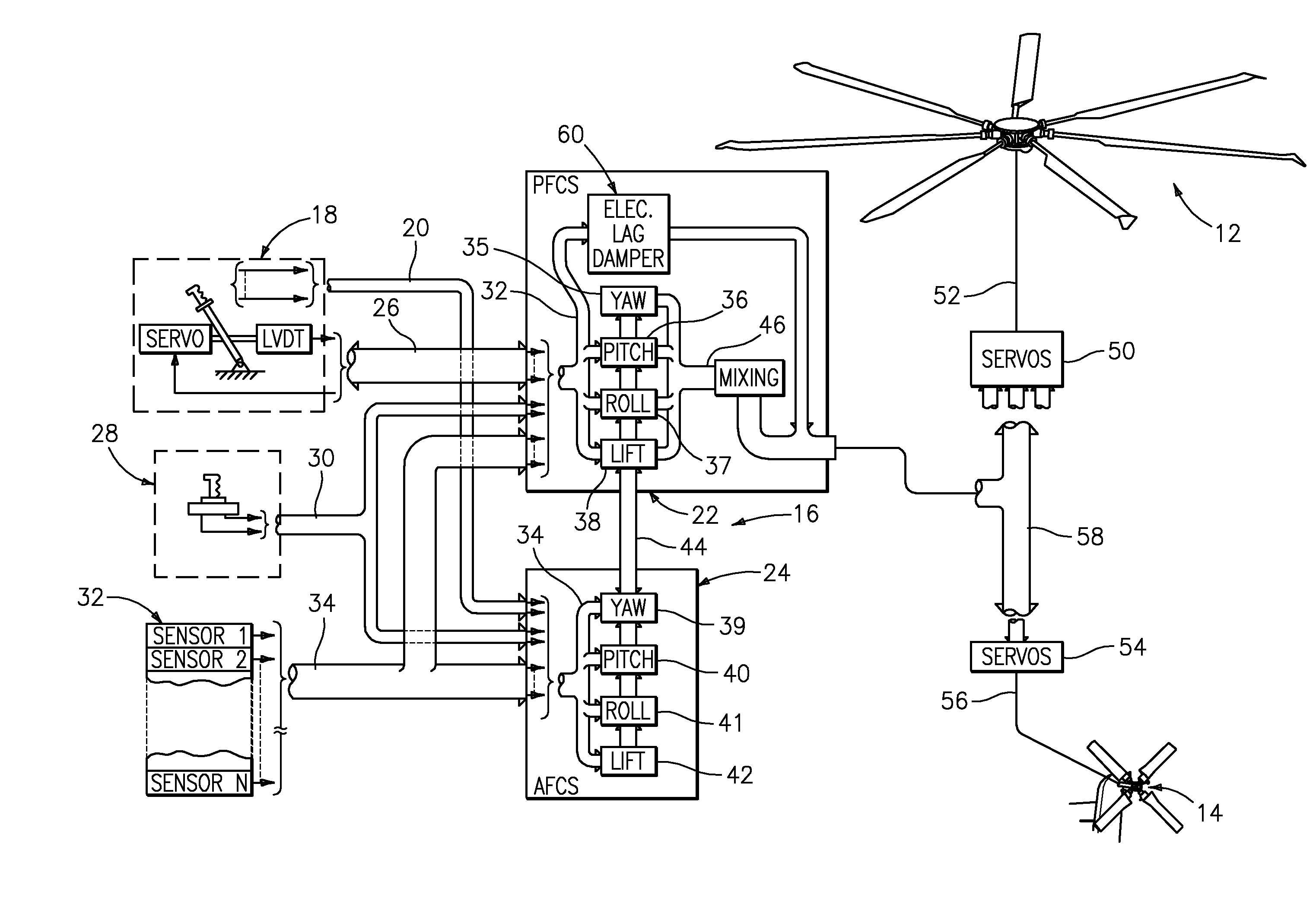
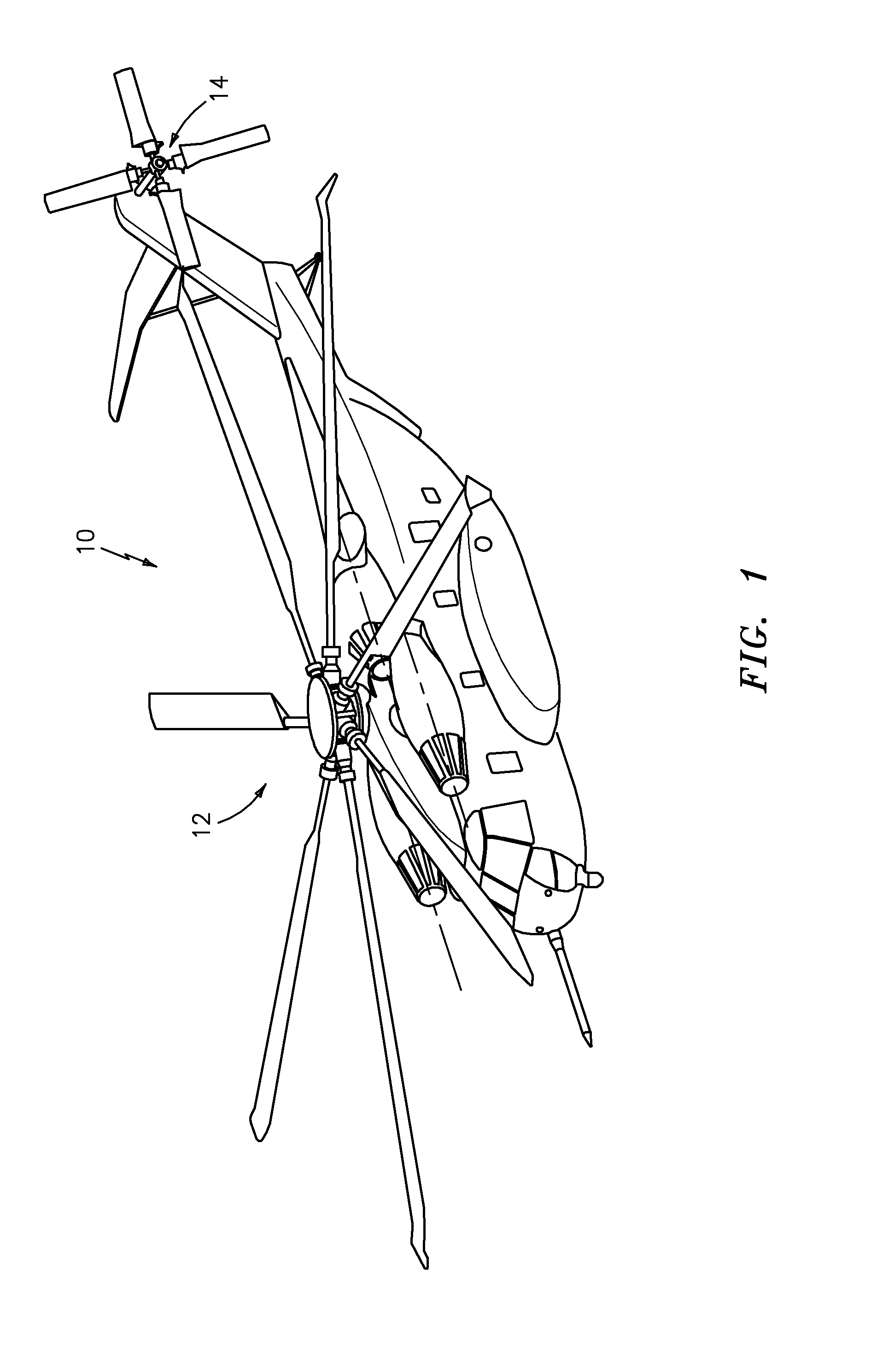
[0014]FIG. 1 illustrates a general perspective view of a helicopter embodiment 10 of a rotary wing aircraft for use with the present invention. The helicopter includes a main rotor assembly 12 and tail rotor assembly 14. Although a particular helicopter configuration is illustrated and described in the disclosed embodiment, other configurations and / or machines, such as high speed compound rotary wing aircraft with supplemental translational thrust systems, dual contra-rotating, coaxial rotor system aircraft, turbo-props, tilt-rotors and tilt-wing aircraft, will also benefit from the present invention.

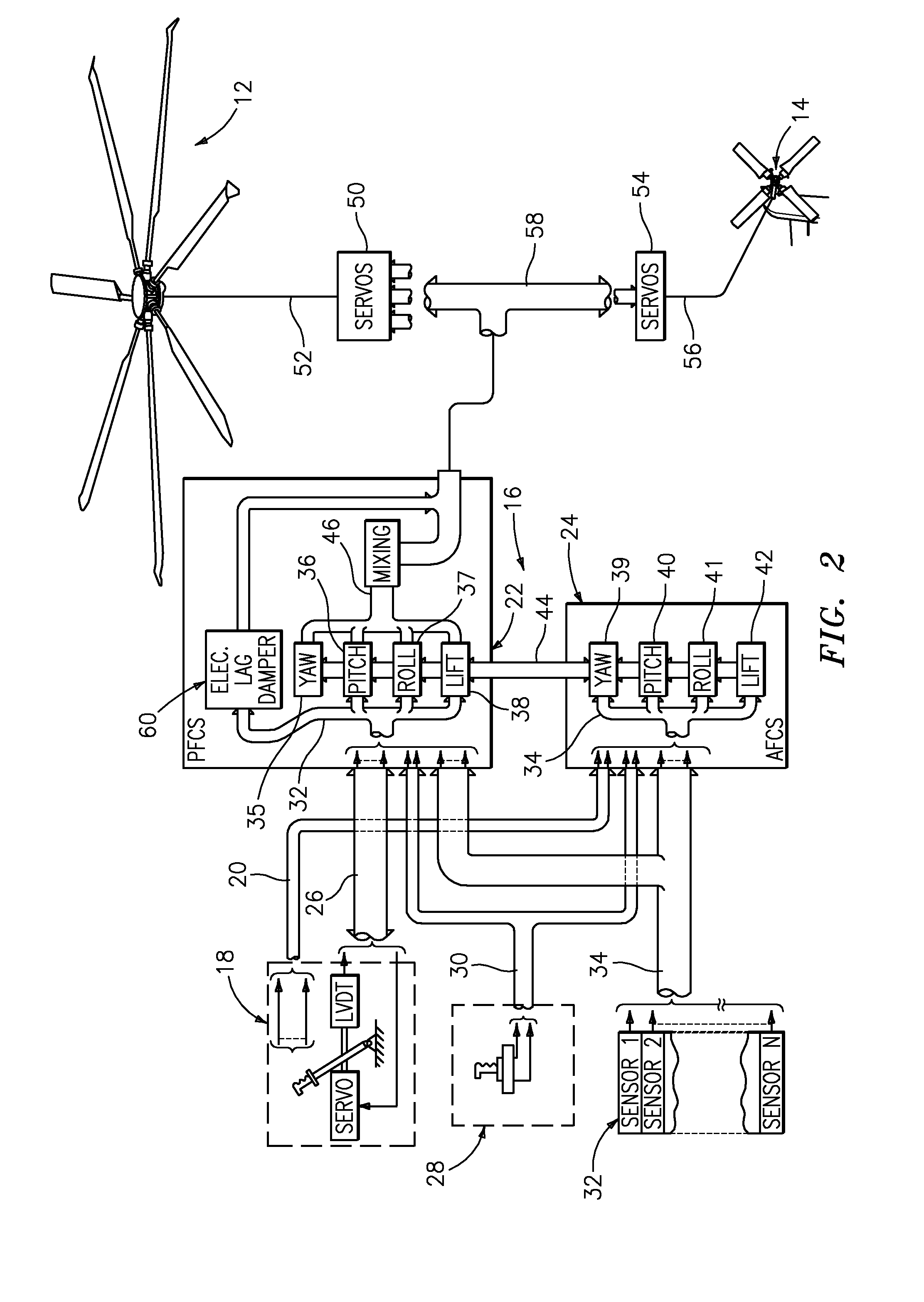
[0015]Referring to FIG. 2, a fly-by-wire type flight control system 16 includes a model following control system which shapes the pilot's controller and displacement commands through an inverse vehicle model to produce the desired aircraft response. The system includes a Primary Flight Control System (PFCS) 22 and an Automatic Flight Control System (AFCS) 24.

[0016]The PFCS 22 is the fli...


PUM


Abstract

An electronic lead / lag damper algorithm implemented as part of the fly-by-wire flight control system to minimize or eliminate mechanical lead / lag dampers of a rotary wing aircraft. The electronic lead / lag damper algorithm uses a cross-feed control methodology that band-pass filters pitch and roll rates and feeds back a signal to the lateral and longitudinal cyclic inputs to provide electronic stability to rotor lag modes.

Description

BACKGROUND OF THE INVENTION[0001]The present invention relates to a fly-by-wire flight control system, and more particularly to an electronic lag damper algorithm implemented as part of the fly-by-wire flight control system which augments a mechanical lead / lag damper for a rotor system of a rotary wing aircraft.[0002]Rotary-wing aircraft include lead / lag dampers to increase rotor blade lead / lag mode damping characteristics. The damper assembly reacts against lead / lag motions of each rotor blade assembly of the rotor system to dampen vibration. Typically, the dampers are sized for a variety of considerations including the need to stabilize ground resonance of the rotary-wing aircraft.[0003]Although effective, current dampers operate under high pressures and may require relatively comprehensive maintenance attention. Furthermore, as each rotor blade requires a lead / lag damper, the dampers increase the overall structural envelope and weight of the rotor system such that aircraft weight...

Claims


Application Information

Patent Timeline
Patent Type & Authority Applications(United States)
IPC IPC(8): F01D7/02B64C27/51G06F7/00
CPCG05D1/0858B64C13/503
Inventor SAHASRABUDHE, VINEETGOLD, PHILIP J.
Owner SIKORSKY AIRCRAFT CORP
Why Eureka
Eureka Blog
Learn More