
Cast saw

Inactive Publication Date: 2010-02-04
LEHMAN JONATHAN +1
View PDF31 Cites 3 Cited by
  • Summary
  • Abstract
  • Description
  • Claims
  • Application Information

AI Technical Summary

Benefits of technology

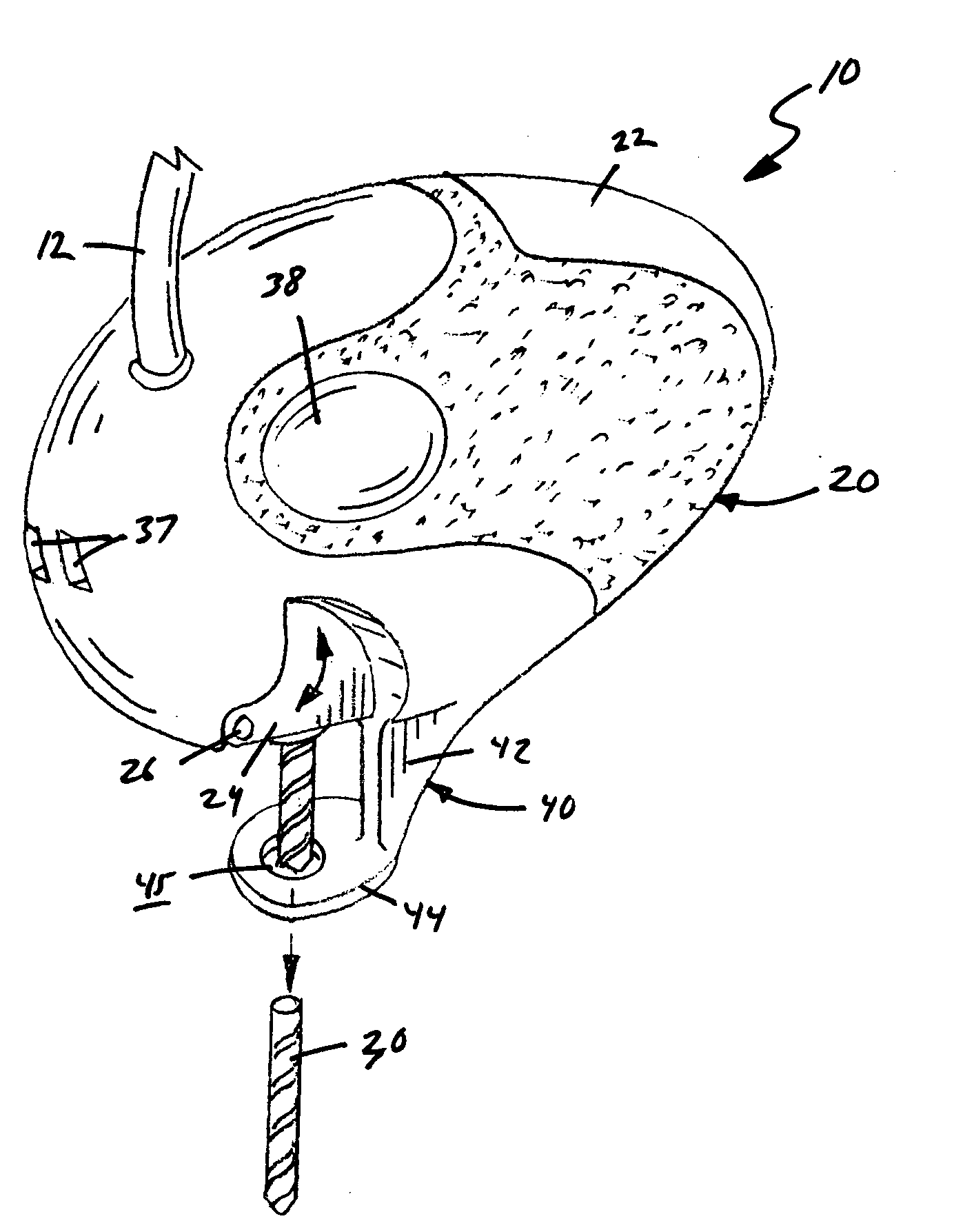
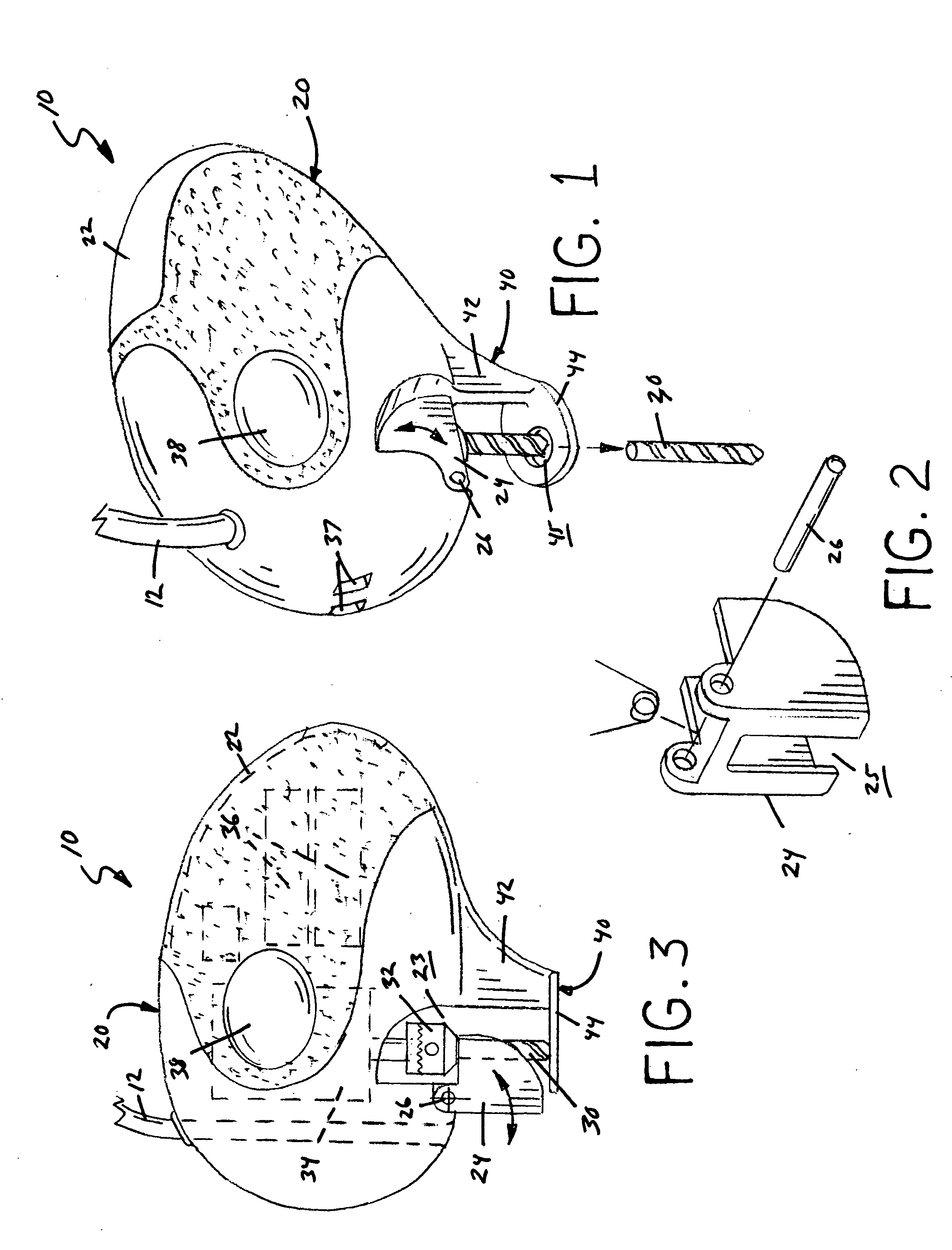
[0004]The cast saw embodying the present invention provides an ergonomically improved design, which eliminates the exposed circular blade of conventional cast saws. The cast saws embodying the present invention include an egg shaped saw body and a spiral cut blade, which extends from the bottom of the saw body. The spiral cut blade is driven by an electric DC drive motor, which is housed within the saw body along with batteries and the other saw electronics and wiring. A blade shield is pivotally mounted to the saw body, which covers the spiral cut blade when not in use. The shield pivots upward against the saw body as the cast saw moves over and cuts the cast from the patient. A guide assembly extends from the bottom of the saw body, which includes a thin neck part and a flat foot plate. The foot plate acts as a guide, which travels between the patient's skin and the inside layer of gauze of the cast. The foot plate also ensures that the spiral cut blade never contacts the patient's skin.
[0005]The operation and appearance of the cast saws of this invention is safer and much less ominous and imposing to patients than conv

Problems solved by technology

While generally safe, conventional cast saws have an ominous appearance and can cause skin burns.
The cutting action cause the blade to become hot and even with experienced operators the contact between the blade and the patient's skin often results in skin burns.
Moreover, the visibly exposed circular blade is naturally unsettling to patients, particularly children.
The cutting action of the vibrating circular blade also creates considerable noise, vibrations and cast dust, which further adds to the patient's anxiety while a cast is removed.

Method used


Image

  • Cast saw
  • Cast saw
  • Cast saw

Examples


Embodiment Construction

[0022]The embodiments herein described are not intended to be exhaustive or to limit the invention to the precise form disclosed. They are chosen and described to explain the invention so that others skilled in the art might utilize its teachings.

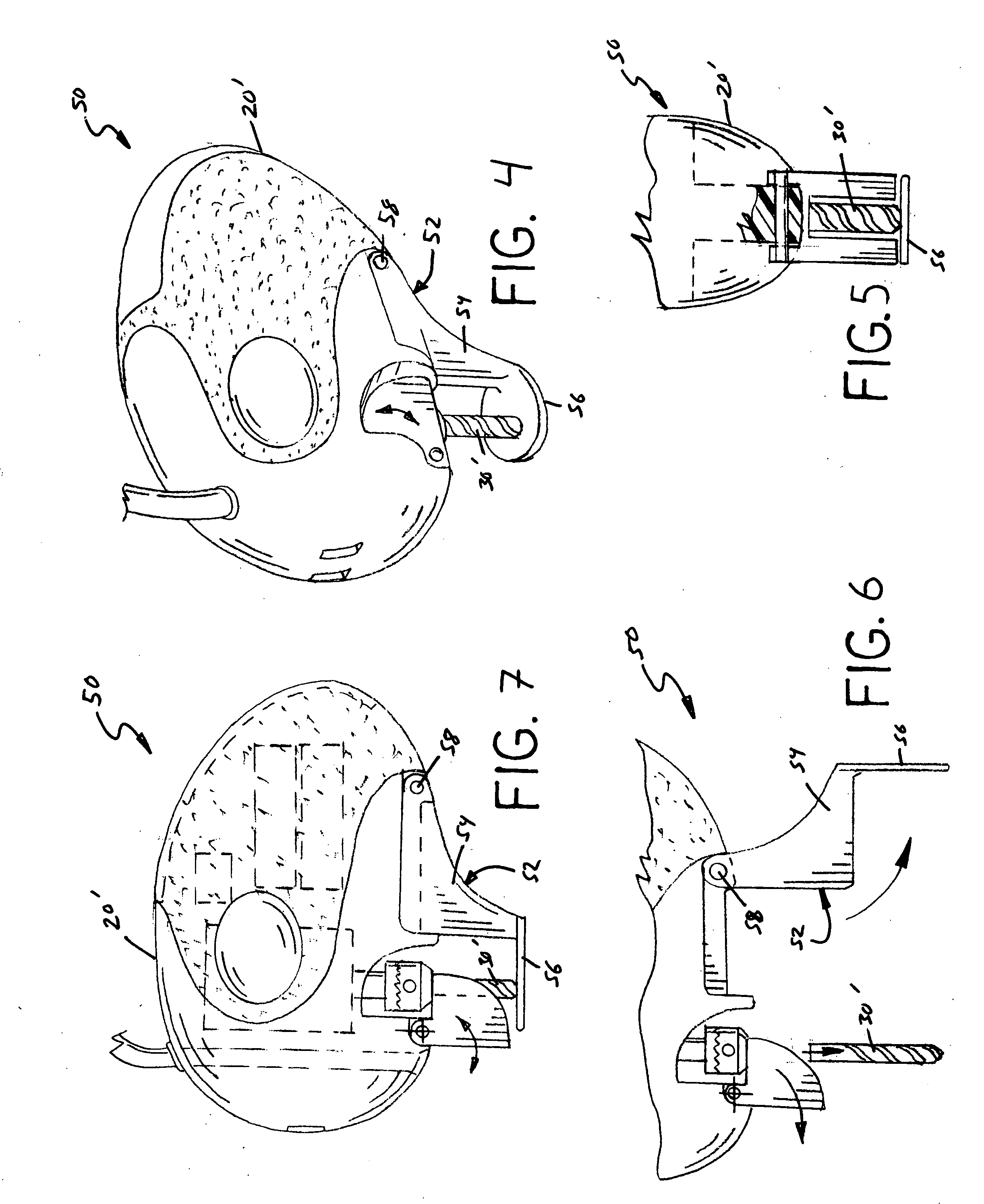
[0023]FIGS. 1-3, 12-14 illustrate a first cast saw embodiment of this invention, which is designated generally as reference numeral 10. As shown, saw 10 includes an egg shaped saw body and a spiral cut blade 30, which is also known as a rotary cut blade. Saw body 20 is configured in an ergonomic egg shape so that the saw body can be comfortably grasped and controlled during the cutting operation. As shown, saw body 20 has rounded front and aft ends. The sides of saw body 20 are also textured to provide a positive grip for the operator. A blade shield 24 is pivotally mounted to saw body 20. Blade shield 24 covers spiral cut blade 30 when not in use and pivots upward against the saw body 20 as cast saw 10 moves over and cuts a cast 4. Blade s...


PUM


Abstract

The cast saws embodying this invention include an ergonomic egg shaped saw body and a spiral cut blade, which eliminates the exposed circular blade of conventional cast saws. The spiral cut blade extends from the bottom of the saw body. The spiral cut blade is driven by an electric DC drive motor, which is housed within the saw body along with batteries and other electronics and wiring. A blade shield is pivotally mounted to the saw body, which covers the spiral cut blade when not in use. The shield pivots upward against the saw body as the cast saw moves over and cuts the cast from the patient. A guide assembly extends from the bottom of the saw body, which includes a thin neck part and a flat foot plate. The foot plate acts as a guide, which travels between the patient's skin and the inside layer of gauze of the cast. The foot plate also ensures that the spiral cut blade never contacts the patient's skin.

Description

[0001]This invention relates to a cast saw, and in particular spiral cut cast saws.BACKGROUND AND SUMMARY OF THE INVENTION[0002]Cast saws are well known in the medical profession. The design of a cast saw has changed little since first being developed to cut through the plaster and other hardened cast materials. A conventional cast saw comprises a cylindrical metal body housing the saw motor and an exposed vibrating or reciprocating circular blades extending from the end of the saw body. The physician simply grasped the saw by the cylindrical body and uses the vibrating blade to cut away the cast from the patient.[0003]While generally safe, conventional cast saws have an ominous appearance and can cause skin burns. Conventional cast saws cut through the cast materials in an up and down stepped action and the circular blade frequently contacts the patient's skin. The cutting action cause the blade to become hot and even with experienced operators the contact between the blade and the...

Claims


Application Information

Patent Timeline
IPC IPC(8): B26D7/01
CPCA61F15/02
Inventor LEHMAN, JONATHANLEHMAN, BENJAMIN
Owner LEHMAN JONATHAN
Learn More