Mechanism based reactive planar suspension

a technology of mechanical and planar suspension, applied in the field of suspension systems, can solve the problems of inconvenient use, difficulty in maneuvering the wheelchair, and difficulty in going over any type of surface other than a smooth surface, and achieve the effect of reducing the unsprung mass of the vehicl

Inactive Publication Date: 2010-02-04
KHAJEPOUR AMIR +2
View PDF7 Cites 2 Cited by
  • Summary
  • Abstract
  • Description
  • Claims
  • Application Information

AI Technical Summary

Benefits of technology

[0005]Accordingly, it is an object of the present invention to provide an improved reactive suspension system that obviates and mitigates from the disadvantages and limitations of the prior art.
[0009]Another objective in a preferred embodiment of the present invention is to provide a suspension system which allows a vehicle to use a harder tire with a lower profile without sacrificing comfort or performance.
[0011]Yet another objective in a preferred embodiment of the present invention is to provide a suspension that reduces the unsprung mass of a vehicle.
[0013]The present suspension has significant advantages over prior art suspensions. While conventional suspensions restrict a vehicle's axle to a single or fixed path, the current suspension allows the vehicle's axle to travel any two-dimensional path. The axle travel path of the current suspension is determined by the input, i.e. for any given input, the suspension responds with the travel path that best absorbs the energy of the input.
[0014]Since a vehicle's axle is not restricted to a defined travel path, like fixed linear or fixed curved path, the current suspension can react to a new input at any point of a travel path and create a new reactive travel path. Additionally, since the recovery travel of the suspension is not tied to the impact path, the suspension can recover faster than prior art suspensions.

Problems solved by technology

In either case, the ride and shocks caused to the occupant can cause injury and discomfort.
Further, the rider can have a difficult time maneuvering the wheelchair.
Going over any type of surface other than a smooth surface can be challenging.
It is rare that a vehicle only encounters one impact or simple disturbance when traversing an obstacle or “input”.
Instead, a wheel is likely to encounter impacts that do not coincide with the travel path.
The problem with prior art suspensions is that they do not effectively absorb loads resulting from such impacts.

Method used


Image

  • Mechanism based reactive planar suspension
  • Mechanism based reactive planar suspension
  • Mechanism based reactive planar suspension

Examples


Embodiment Construction

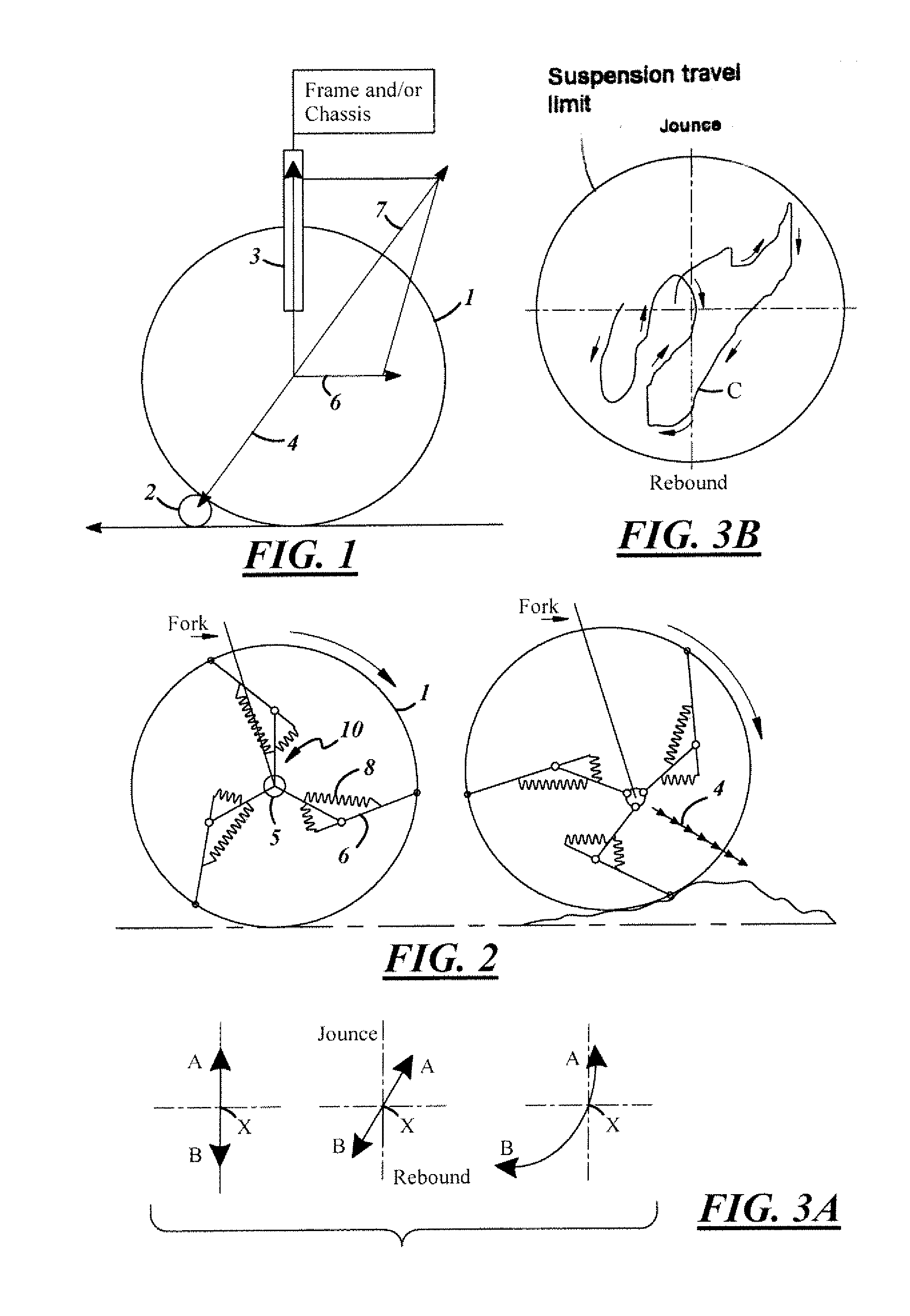
[0027]With reference to FIG. 1, this is a schematical representation of the limitations of current suspensions. Current suspensions are not fully effective at absorbing all of the energy encountered by a wheel contacting an obstacle. As can be seen in the Figure, a wheel 1 encountering an input in the nature of obstruction 2 can move only in the fixed linear path permitted by the suspension. Accordingly, while some of the energy from the impact is absorbed by the suspension's springs or shock absorbers 3, or a combination thereof, a vectored component 7 normal to impact reaction line 4 is transferred directly to the chassis along the direction line 6.

[0028]Ideally therefore, rather than a suspension that has a single or fixed path, it is preferable that the path of suspension travel when reacting to an input is the path that will best absorb the input's energy. So instead of the predetermined path of travel in a conventional system, the present reactive suspension proposes that its ...


PUM


Abstract

A suspension for a wheel rotatably mounted about an axle, comprising means to resiliently support the axle from movement in the plane of the wheel's rotation in response to an input to the wheel.

Description

FIELD OF THE INVENTION[0001]The present invention relates generally to a suspension system for the wheel of a vehicle such as a bicycle, automobile or wheelchair, and more particularly to a suspension that resiliently supports the wheel's axle in the plane of wheel rotation within the suspension limits.BACKGROUND OF THE INVENTION[0002]Vehicle suspensions today use some sort of fixed linear and / or curved planar travel path. This includes suspensions directly or indirectly coupled to a spring and / or dampener, suspensions directly or indirectly coupled to a frame, and / or chassis, and passive and / or adaptive suspensions. When a conventional vehicle suspension is compressed, due to a wheel of the vehicle impacting an obstacle, for example, the axle of the vehicle always travels the same path. For purposes of this description, the path that an axle follows during suspension compression is called the “travel path”.[0003]Powered wheelchairs are configured as either mid-drive or rear drive. ...

Claims


Application Information

Patent Timeline
Patent Type & Authority Applications(United States)
IPC IPC(8): B60B9/02
CPCB60B9/02B60B9/26B60B9/06
Inventor KHAJEPOUR, AMIRBOYER, GEOFFREYAZAD, NASSER LASHGARIAN
Owner KHAJEPOUR AMIR
Why Eureka
Try Eureka