Dispensing device arranged to reduce the risk of strain and injury during use

a technology of dispensing device and dispensing device, which is applied in the direction of liquid transfer device, liquid handling, instruments, etc., can solve the problems of back strain or other injury, user may need to twist or contort his or her arm, wrist, hand and other body parts, etc., and achieve the effect of relieving back strain

Active Publication Date: 2010-02-04
ALBION ENG
View PDF18 Cites 1 Cited by
  • Summary
  • Abstract
  • Description
  • Claims
  • Application Information

AI Technical Summary

Benefits of technology

[0005]These and other objects of this invention are achieved by providing a device for dispensing flowable materials to low locations without the user being required to bend over or kneel down during dispensing which provides relief from back strain or other injuries. The device includes a cylinder having a piston mounted therein which reciprocates between forward ejecting and return directions. A driven rod, connected to the piston, extends through a front wall of the cylinder. Upon actuation, a trigger mechanism supplies a pressure medium within the cylinder for displacing the piston in the forward ejecting direction to dispense flowable material from the dispensing device. The trigger mechanism is oriented to enable the user to hold the dispensing device like a suitcase and is spaced a sufficient distance from where the flowable material is dispensed to enable a user to remain standing erect while dispensing to low areas such as where a floor and wall meet. Moreover, the trigger mechanism is positioned and oriented to allow a more comfortable dispensing position when such low locations are in areas which are difficult to access.

Problems solved by technology

Such commercially available dispensing devices have several drawbacks, especially when applying flowable material to low locations, such as along the perimeter of a room or a shower stall where the wall meets the floor.
The main drawback is that due to the location and orientation of the trigger mechanism on such dispensing devices, it is usually necessary for the user to bend over, kneel down, or squat towards the floor to accurately apply the flowable materials to such low locations.
Another drawback associated with the location and orientation of the trigger mechanism on commercially available dispensing devices is that the user may need to twist or contort his or her arm, wrist, hand, and other body part when using such a commercially available dispensing device to apply flowable material to low locations that are difficult to access.
This can be an uncomfortable operation for many users, and may result in back strain or other injury.
Because it is physically difficult for some users to dispense flowable materials to such low locations using a conventional dispensing device, the material may not be properly applied.

Method used


Image

  • Dispensing device arranged to reduce the risk of strain and injury during use
  • Dispensing device arranged to reduce the risk of strain and injury during use
  • Dispensing device arranged to reduce the risk of strain and injury during use

Examples


Embodiment Construction

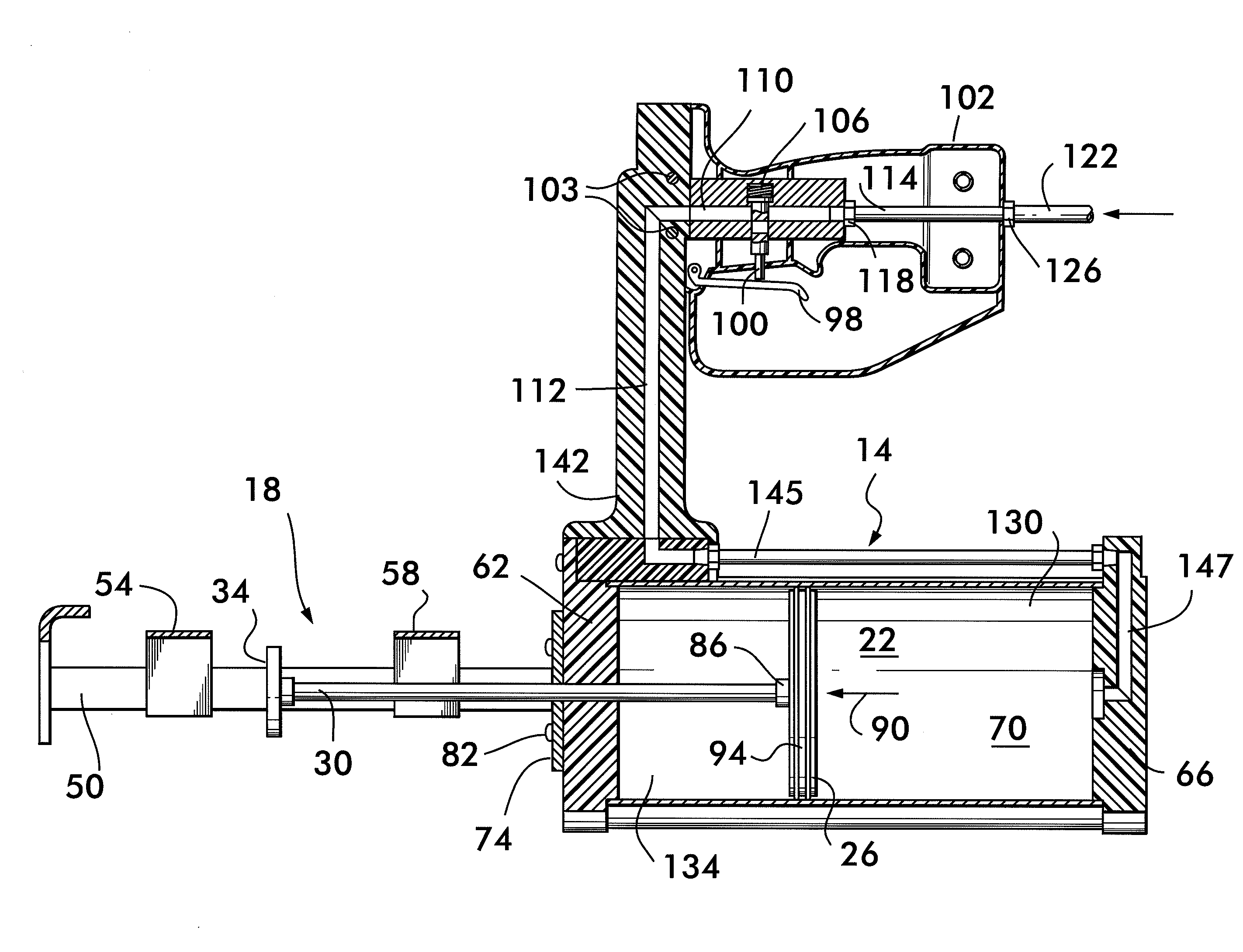
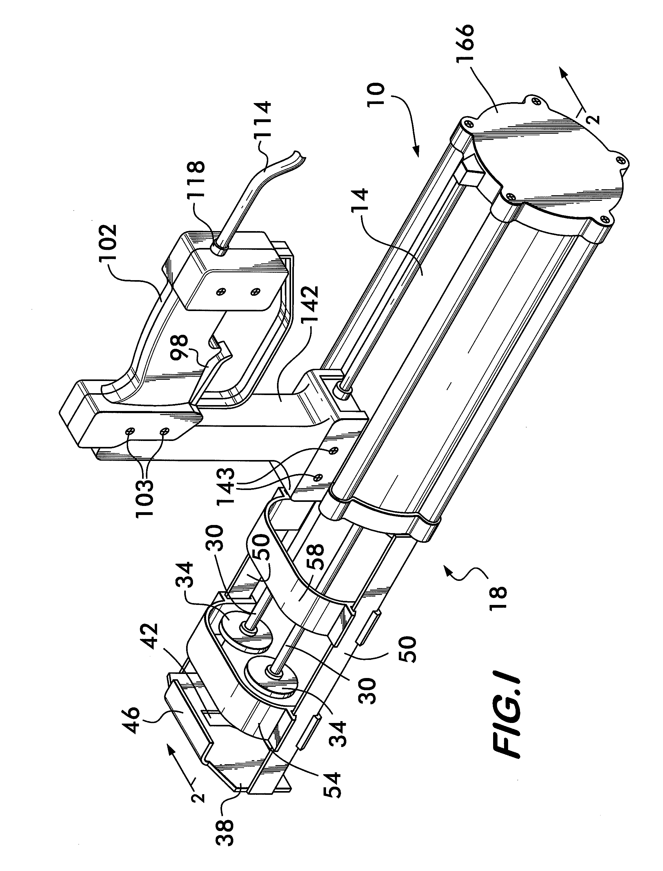
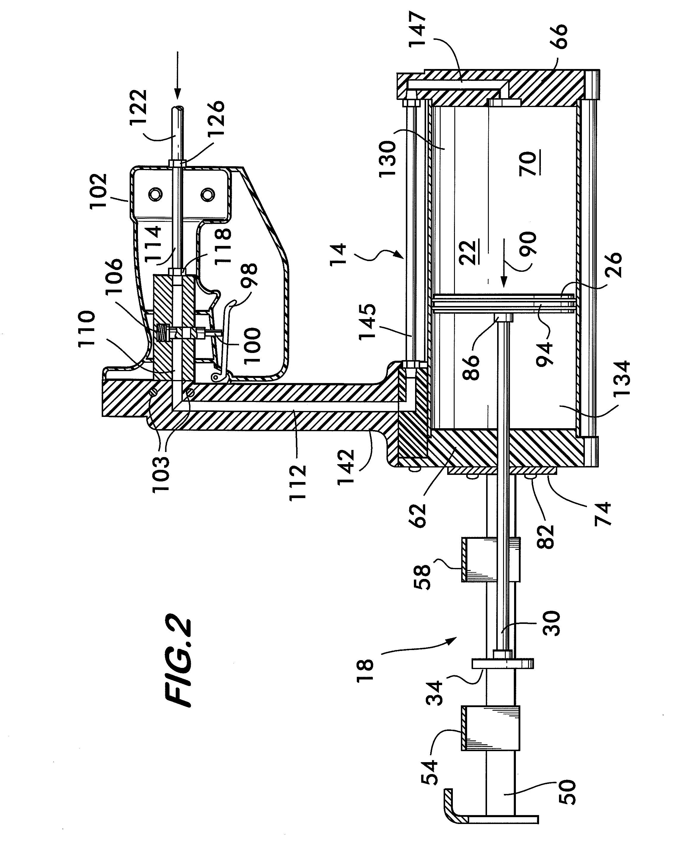
[0011]Referring now to the drawings, a device for dispensing materials in accordance with the present invention is shown generally at 10 in FIGS. 1 and 2. The dispensing device 10 includes a rearward driving section 14 and a forward section in the form of a dual component carriage assembly 18 of conventional design for housing a composition to be dispensed. The rearward driving section 14 includes an air cylinder assembly 22 (FIG. 2) within which there is positioned a piston 26. As best shown in FIGS. 1 and 2, the piston 26 operates two driven rods 30 which terminate in ejector rams 34.

[0012]Referring now to FIG. 1, the dual component carriage assembly 18 houses a plurality, e.g., two, cartridge assemblies (not shown) containing components to be dispensed. It should be understood that the carriage assembly 18 can be of any desired construction for housing a composition to be dispensed and does not constitute a limitation on the present invention. For example, although the embodiment...


PUM


Abstract

A device for dispensing flowable materials to low locations without the user being required to bend over or kneel down during dispensing provides relief from back strain or other injuries. The device includes a cylinder having a piston mounted therein which reciprocates between forward ejecting and return directions. A driven rod, connected to the piston, extends through a front wall of the cylinder. Upon actuation, a trigger mechanism supplies a pressure medium within the cylinder for displacing the piston in the forward ejecting direction to dispense flowable material from the dispensing device. The trigger mechanism is oriented to enable the user to hold the dispensing device like a suitcase and is spaced a sufficient distance from where the flowable material is dispensed to enable a user to remain standing erect while dispensing to low areas such as where a floor and wall meet.

Description

BACKGROUND OF THE INVENTION[0001]The present invention relates to dispensing devices. More particularly, the present invention relates to a dispensing device that enables a user to dispense flowable material to low locations, such as where a floor meets a wall, without requiring the user to bend over, kneel down or squat during dispensing, thus reducing the risk of strain or other back injury. The present invention also reduces the need for the user to contort the arm, wrist, hand, and other body parts, where the low location to which flowable material is to be dispensed is difficult to access.[0002]Commercially available devices for dispensing flowable compositions such as caulking materials, grease, automotive windshield sealant, reactive resins, and the like, generally consist of a rearward driving section and a forward section in the form of a carriage assembly for housing a composition to be dispensed. The rearward drive section includes a cylinder having a front end wall, a re...

Claims


Application Information

Patent Timeline
Patent Type & Authority Applications(United States)
IPC IPC(8): G01F11/00B67D5/52
CPCB05C17/00553E04F21/30B05C17/015
Inventor SCHNEIDER, MARK C.HANNI, JOSEPH B.
Owner ALBION ENG
Why Eureka
Try Eureka