
Plow shovel

a shovel and shovel technology, applied in the field of shovels, to achieve the effect of reducing friction, reducing the amount of thrust needed, and reducing drag

Inactive Publication Date: 2011-11-03
KAPLAN FREDERICK DAVID
View PDF3 Cites 8 Cited by
  • Summary
  • Abstract
  • Description
  • Claims
  • Application Information

AI Technical Summary

Benefits of technology

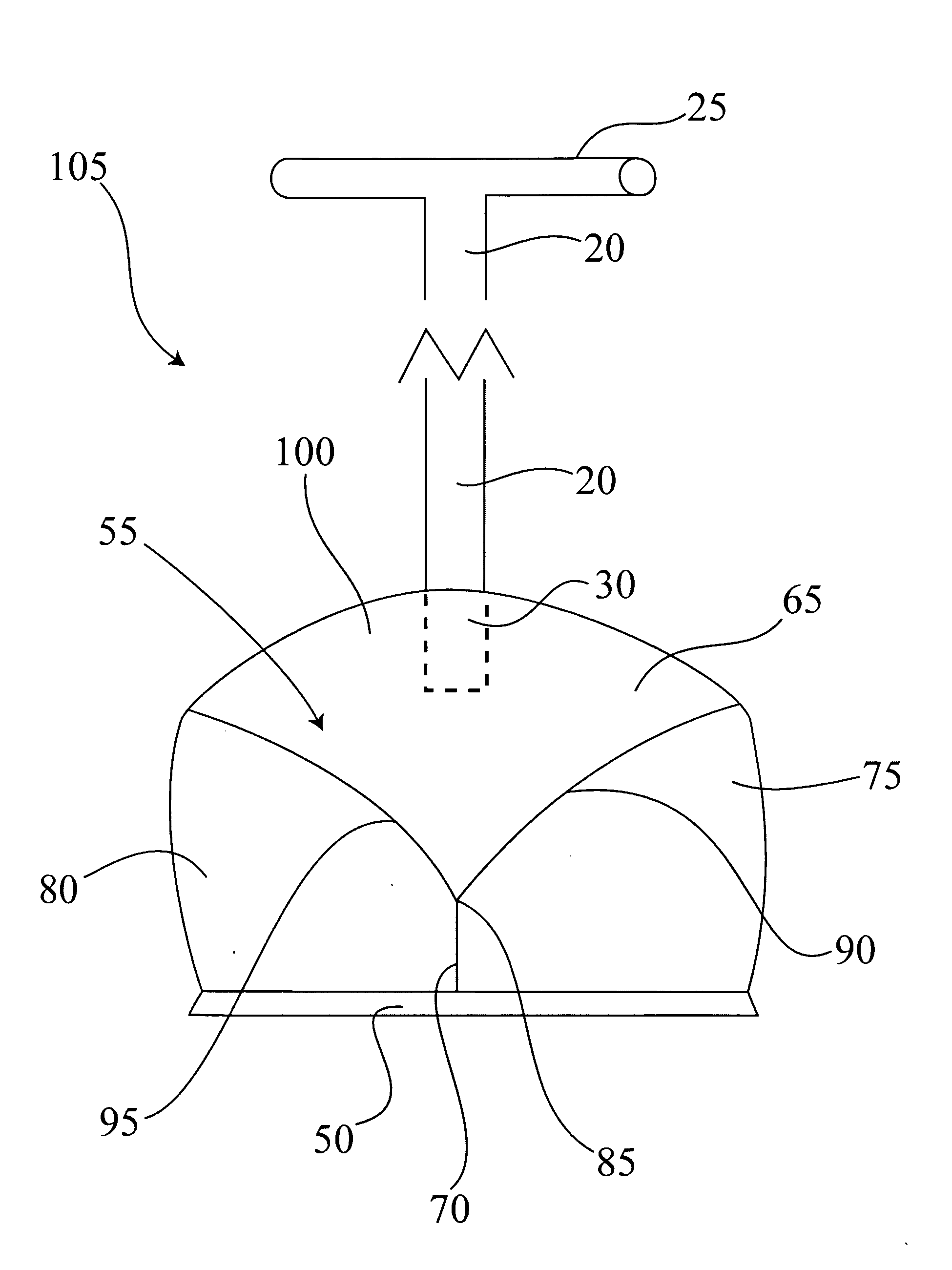
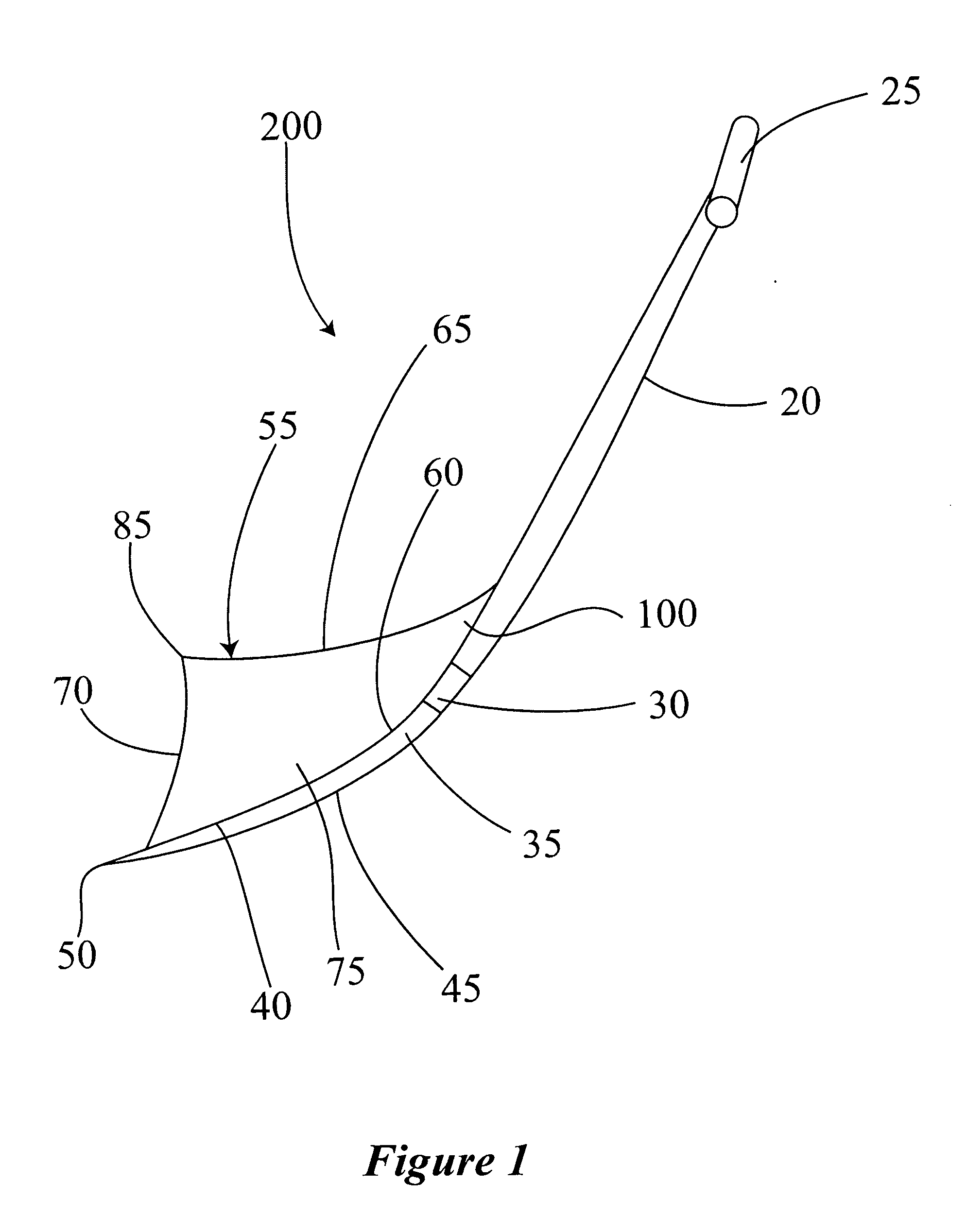
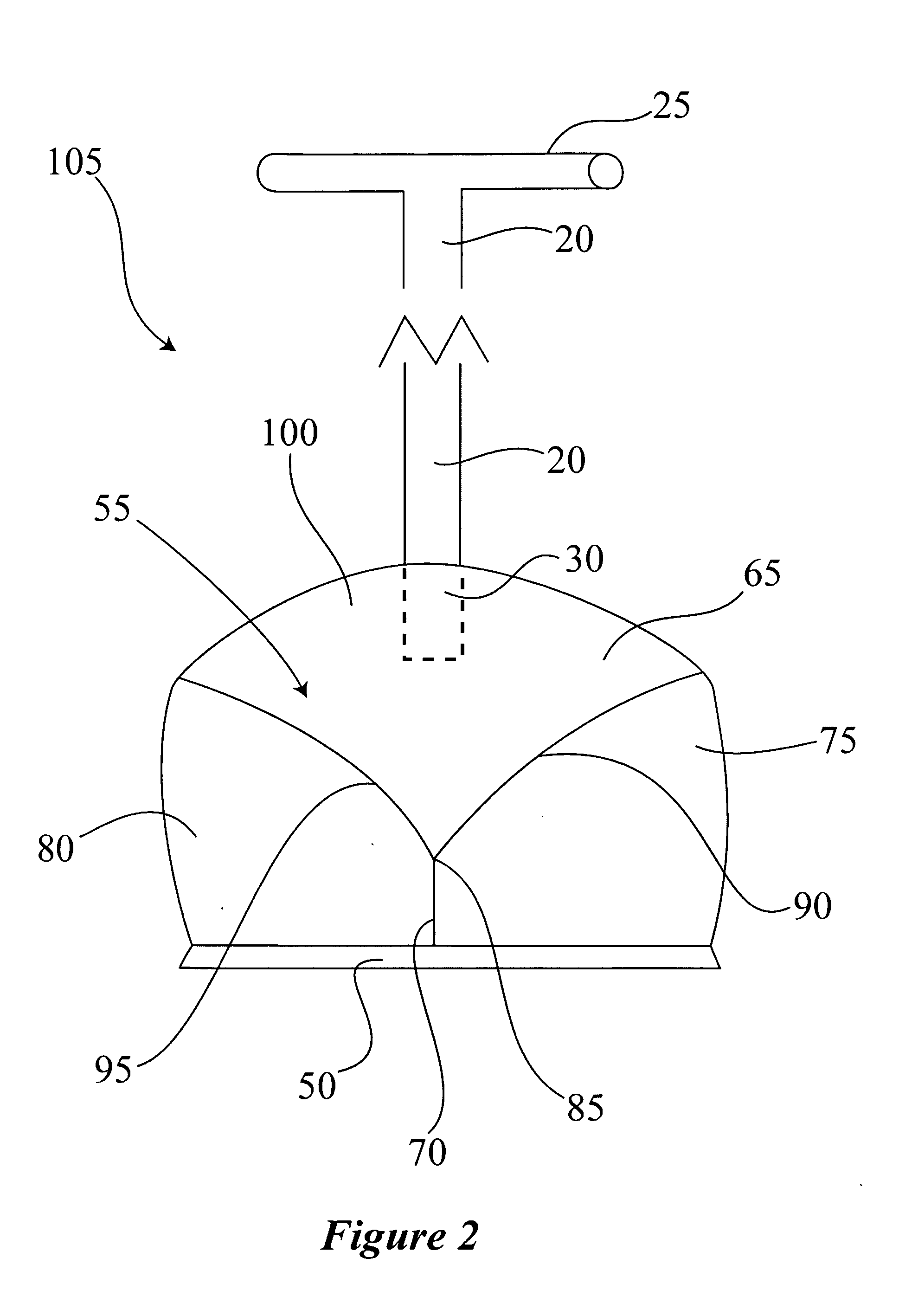
[0007]The configuration of the plow shovel of the present invention in accordance is equipped with several features within the principles of the present invention that allows a person pushing the plow shovel to make a path in the snow without lifting the snow and experiencing back strain. For example, one feature is the shape of the handle. The handle of the plow shovel can be designed to provide amble surface for the user to lean into the shovel so as to provide enough forward thrust to easily and effortlessly make a path in the snow. That is the end portion of the handle is elongated so to have increased surface area that comes in contact with the user while pushing. As further described below the increased surface area of handle displaces the pressure placed on the hands, chest or body of the user when pushing the plow shovel thereby reducing muscle strain. The handle can be padded or separate “handle gloves” can be sold to further cushion the handle.
[0010]In yet another embodiment of the present invention, the plow shovel in accordance with the principles of the present invention further comprises at least one ski runner and / or wheels wherein the ski runners have a flat portion and a curved portion. The flat portion and the curved portion each of the ski-runner have a bottom surface and a top surface wherein the bottom surface is configured to contact the snow covered surface to be plowed when the plow shovel is at an angle between about (30) thirty and about (50) fifty degrees with the ground surface so as to allow the shovel to glide across the surface with reduced friction. The ski runner(s) reduces the amount of thrust necessary to push the shovel through the snow. The snow shovel can also be equipped with wheels that are strategically located behind the scoop and designed to support the weight of the shovel and snow that allows the scoop to move with reduced drag along the snow cleared path. This feature further reduces muscle and back strain when using the plow shovel.

Problems solved by technology

While the devices available in the prior art fulfill their respective, particular objective and requirements, many if not all require the strain of lifting snow off of the ground in order to clear a path on walkways, sidewalks and driveways.

Method used


Image

  • Plow shovel
  • Plow shovel
  • Plow shovel

Examples


Embodiment Construction

[0024]The present invention may be understood more readily by reference to the following detailed description of the invention taken in connection with the accompanying drawing figures, which form a part of this disclosure and in which like numbers indicate like features. It is to be understood that this invention is not limited to the specific devices, methods, conditions or parameters described and / or shown herein, and that the terminology used herein is for the purpose of describing particular embodiments by way of example only and is not intended to be limiting of the claimed invention. Also, as used in the specification and including the appended claims, the singular forms “a,”“an,” and “the” include the plural, and reference to a particular numerical value includes at least that particular value, unless the context clearly dictates otherwise. Ranges may be expressed herein as from “about” or “approximately” one particular value and / or to “about” or “approximately” another part...


PUM


Abstract

A plow shovel configured to create a path in snow by pushing the snow along a surface without lifting the snow. The plow shovel has a handle attached to a scoop having a first side and a second side. The scoop has a multi-sided plow component configured to part snow and makes a path without lifting the shovel as the plow shovel is pushed forward. A method of clearing a path in snow using the plow shovel described is also provided.

Description

CROSS REFERENCE TO RELATED APPLICATIONS[0001]This application claims the benefit of U.S. Provisional Application No. 61 / 343,327, filed Apr. 28, 2010, the contents of which are incorporated herein by reference.FIELD OF THE INVENTION[0002]The present invention relates to a plow shovel and more particularly pertains to a shovel designed to easily create a path in snow by pushing rather than lifting and throwing snow so as to reduce muscle and back strain that is common to shoveling. The shovel may also be used to make paths in materials other than snow, such as sand, gravel, soil, mulch, garbage, man-made materials and combinations thereof.BACKGROUND OF THE INVENTION[0003]The use of snow removal devices is known in the prior art. More specifically, snow removal devices heretofore devised and utilized for the purpose of removing snow are known to consist basically of familiar, expected and obvious structural configurations, notwithstanding the myriad of designs encompassed by the crowde...

Claims


Application Information

Patent Timeline
Patent Type & Authority Applications(United States)
IPC IPC(8): E01H5/02A01B1/00
CPCE01H5/02
Inventor KAPLAN, FREDERICK DAVID
Owner KAPLAN FREDERICK DAVID
Learn More