Forced draft direct vent type room heater

Inactive Publication Date: 2010-02-04
RINNAI CORP
View PDF12 Cites 5 Cited by
  • Summary
  • Abstract
  • Description
  • Claims
  • Application Information

AI Technical Summary

Benefits of technology

[0014]Here, when the drain dish is arranged in the lower space of the combustion housing as in a conventional example, the drain dish is positioned in the lower part of the main heat exchanger, so that a drain formed in the inside of the main heat exchanger can be drained to the drain dish. On the other hand, in the present invention, the drain dish is arranged on the upper wall of the combustion housing, so that the drain formed from the main heat exchanger cannot be drained to the drain dish. Accordingly, it is necessary to set the heat exchange efficiency of the main hea

Problems solved by technology

As a result, a position where the ro

Method used


Image

  • Forced draft direct vent type room heater
  • Forced draft direct vent type room heater
  • Forced draft direct vent type room heater

Examples


Embodiment Construction

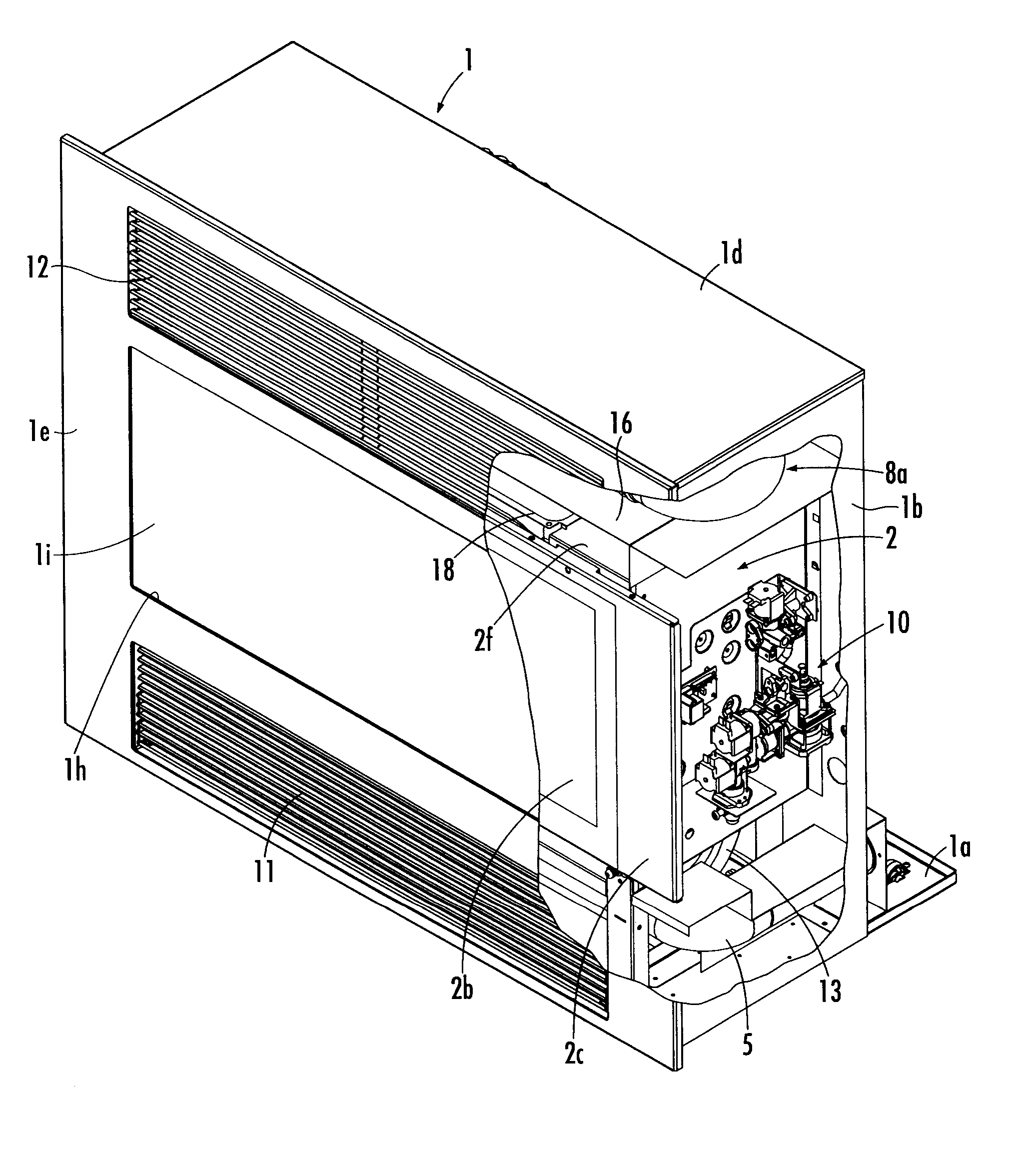
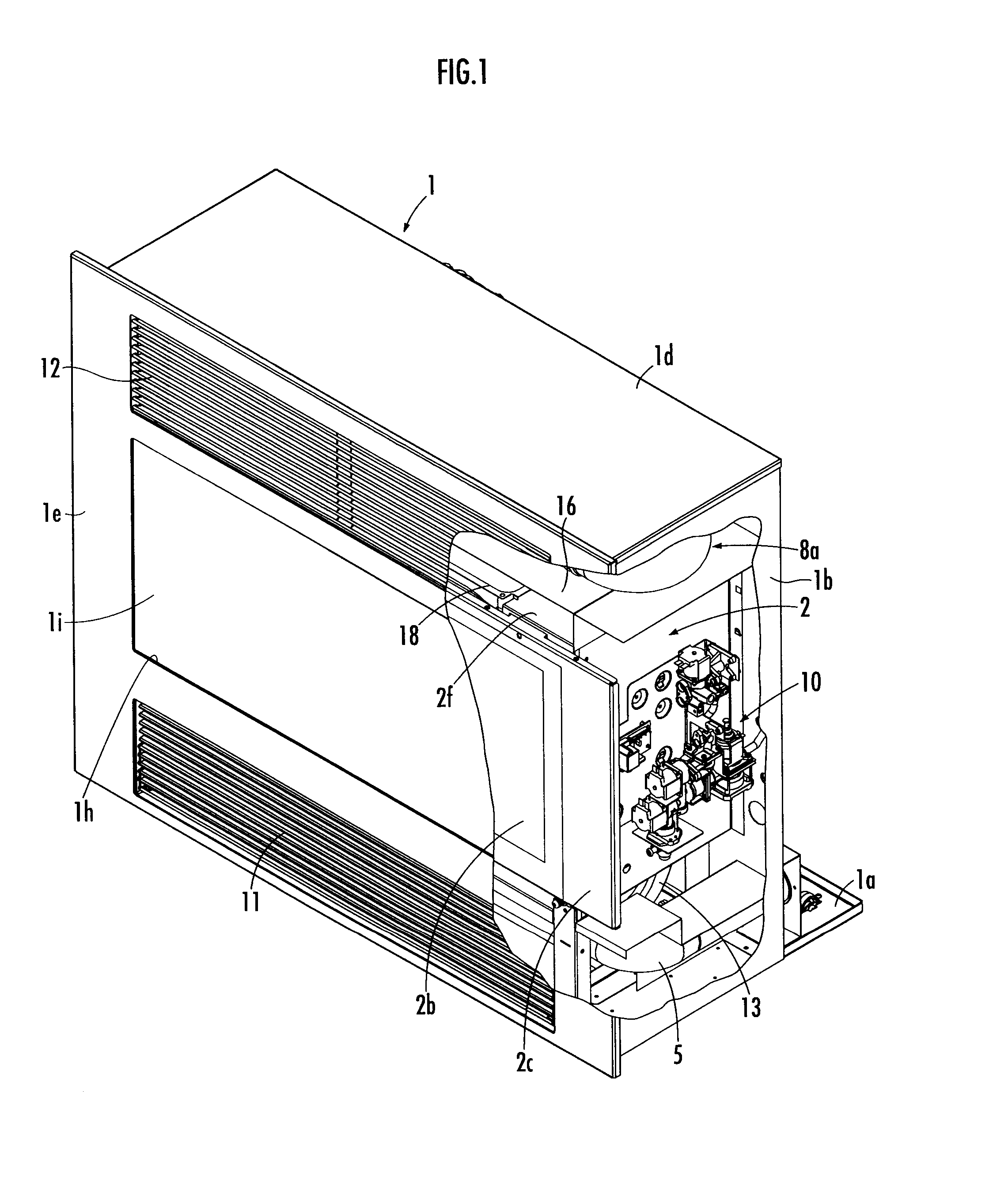
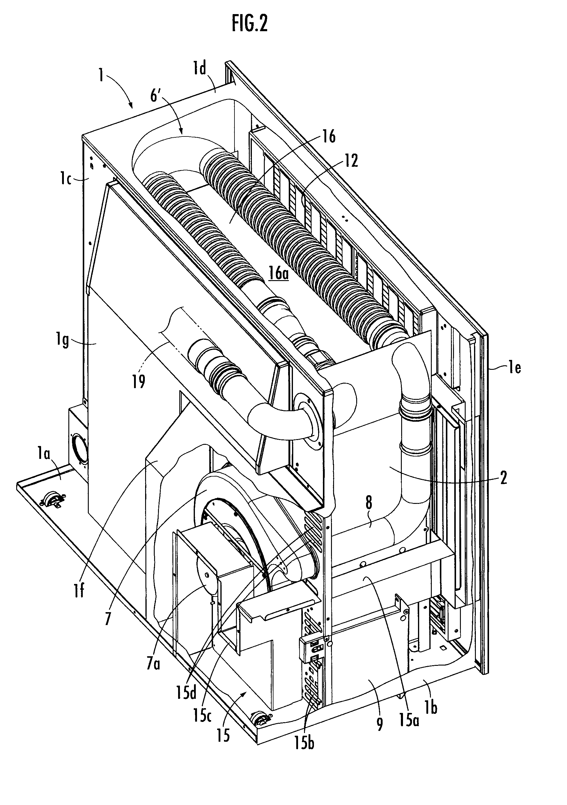
[0019]The embodiment in which the present invention is applied to a fireplace type room heater will now be described below. This room heater comprises an outer case 1 and a combustion housing 2 which is provided in the outer case 1, as is illustrated in FIG. 1 to FIG. 4. The outer case 1 is constituted by a bottom plate 1a, right-and-left side plates 1b, a back plate 1c, an upper plate 1d, a front panel 1e, a first extension case 1f which is installed in a portion closer to one side of the back face of the back plate 1c, and a second extension case 1g which is installed from the other half side of the back face of the back plate 1c to the upper part of the first extension case 1f.

[0020]A burner 3 and a pilot burner 3a for igniting the burner 3 are arranged in the lower part of the inside of the combustion housing 2. In addition, a burner supporting plate 2a in which an opening for fitting the upper end part of the burner 3 is formed is arranged in the combustion housing 2, and a fa...


PUM


Abstract

A vent hole 12 is provided in the upper part of a front panel 1e of an outer case 1. Air in a room having passed through a section in which a main heat exchanger 6 is arranged is led to the vent hole 12 through a space between an upper plate 1b of an outer case 1 and an upper wall 2d of a combustion housing 2. A drain dish 18 is arranged on the upper face of the upper wall 2d of the combustion housing 2.

Description

BACKGROUND OF THE INVENTION[0001]1. Field of the Invention[0002]The present invention relates to a forced draft direct vent type room heater which forcibly supplies air for combustion and exhausts a combusted gas.[0003]2. Description of the Related Art[0004]Conventionally, such a room heater is known as is described in Japanese Patent No. 4050744. This room heater has a burner housed in a combustion housing provided in an outer case. In the combustion housing, air for combustion is supplied and a combusted gas is exhausted by a combustion fan. In an exhaust path for exhausting the combusted gas therethrough, a main heat exchanger is provided in the upstream side, and a supplementary heat exchanger is provided in the downstream side. In the outer case, an air intake and a vent hole are provided. In the outer case, a warm air fan is provided, and this warm air fan takes in room air from the air intake and sends the air to the inside of the room from the vent hole through the main heat...

Claims


Application Information

Patent Timeline
IPC IPC(8): F24D5/02
CPCF24H9/0063F24H9/0073F24B1/1808F24H3/067F24D19/0087F24D2200/10F24H3/027F24C3/004Y02B30/00
Inventor KANEIWA, SATOSHI
Owner RINNAI CORP
Why Eureka
Try Eureka