Heat sink

a heat sink and heat pipe technology, applied in the field of heat sinks, can solve problems such as degrading thermal exchange efficiency, and achieve the effects of reducing heat pipe size, and improving heat exchange or radiating efficiency of heat pipes within a limited spa

Inactive Publication Date: 2008-08-28
THE FUJIKURA CABLE WORKS LTD
View PDF18 Cites 22 Cited by
  • Summary
  • Abstract
  • Description
  • Claims
  • Application Information

AI Technical Summary

Benefits of technology

[0020]According to the present invention, the heat pipe is bent into arcuate and such a curved portion is contacted sequentially with the plurality of fins, and one of the end portions of the heat pipe is connected to the heat receiving base. This structure allows the heat pipe to be contacted with the fins over a long range. For this reason, heat exchange or radiating efficiency of the heat pipe within a limited space can be improved significantly. Meanwhile, the fins mounted on the heat pipe are not shared by another heat pipe. Therefore, heat exchange can be carried out efficiently without enlarging the fins. In other words, this is advantageous to downsize the heat pipe. Thus, the heat pipe of the invention can also comply with a demand of reduction in size and weight of an electronic control unit of various types of equipments. Further, according to the present invention, the heat receiving base as a core of the heat sink is structured as a heat pipe, and one of the end portions of the heat pipes bent into arcuate are connected thereto. This structure also improves heat transfer efficiency and heat exchange efficiency of the heat sink as a whole. Specifically, according to the invention, a porous structured wick is formed on an interior bottom face of the heat receiving base, and porous structured protrusions are formed thereon. Therefore, heat transporting capacity of the heat sink is further enhanced, and heat exchange efficiency between the heat sink and the exothermic element is thereby improved.

Problems solved by technology

As a result, thermal resistance of the vertical fins is increased and this degrades thermal exchange efficiency.

Method used


Image

  • Heat sink
  • Heat sink
  • Heat sink

Examples


first embodiment

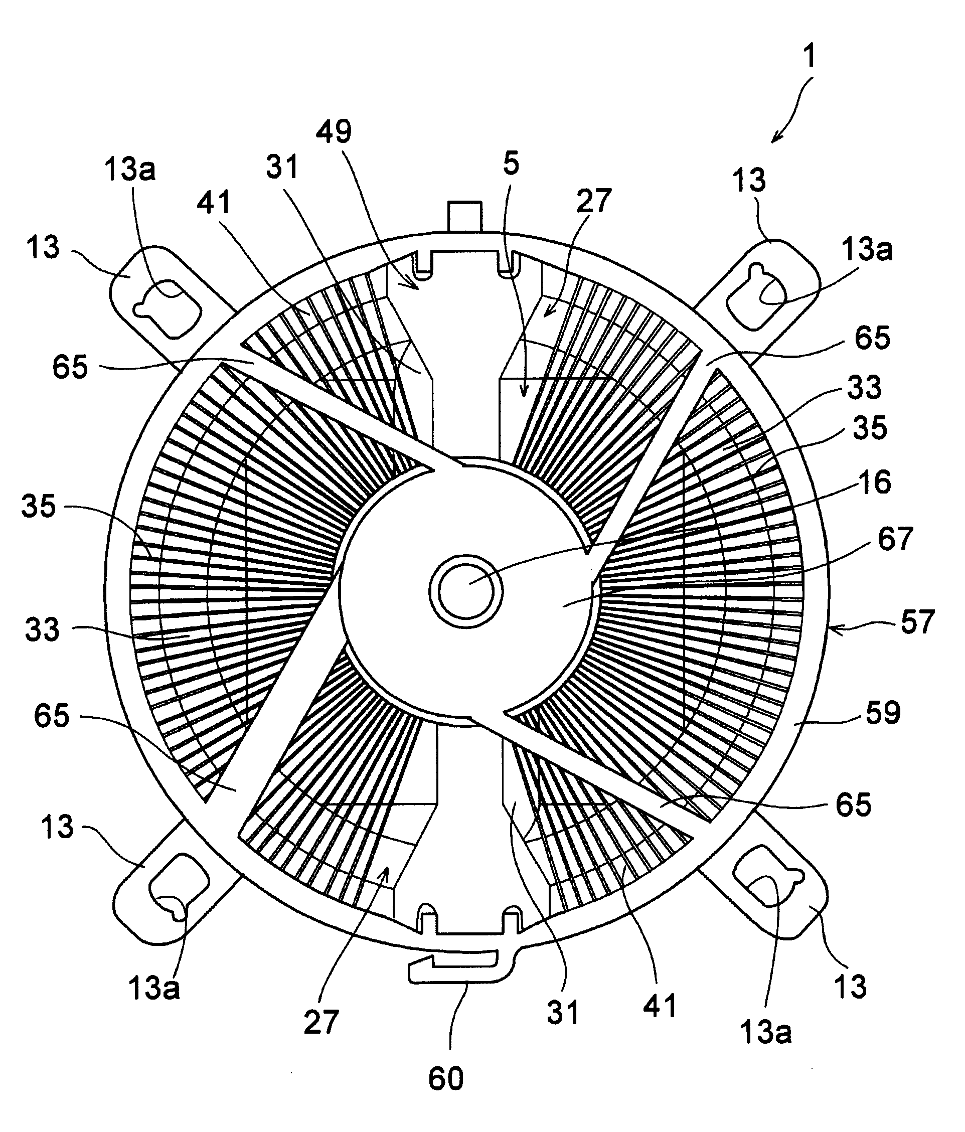
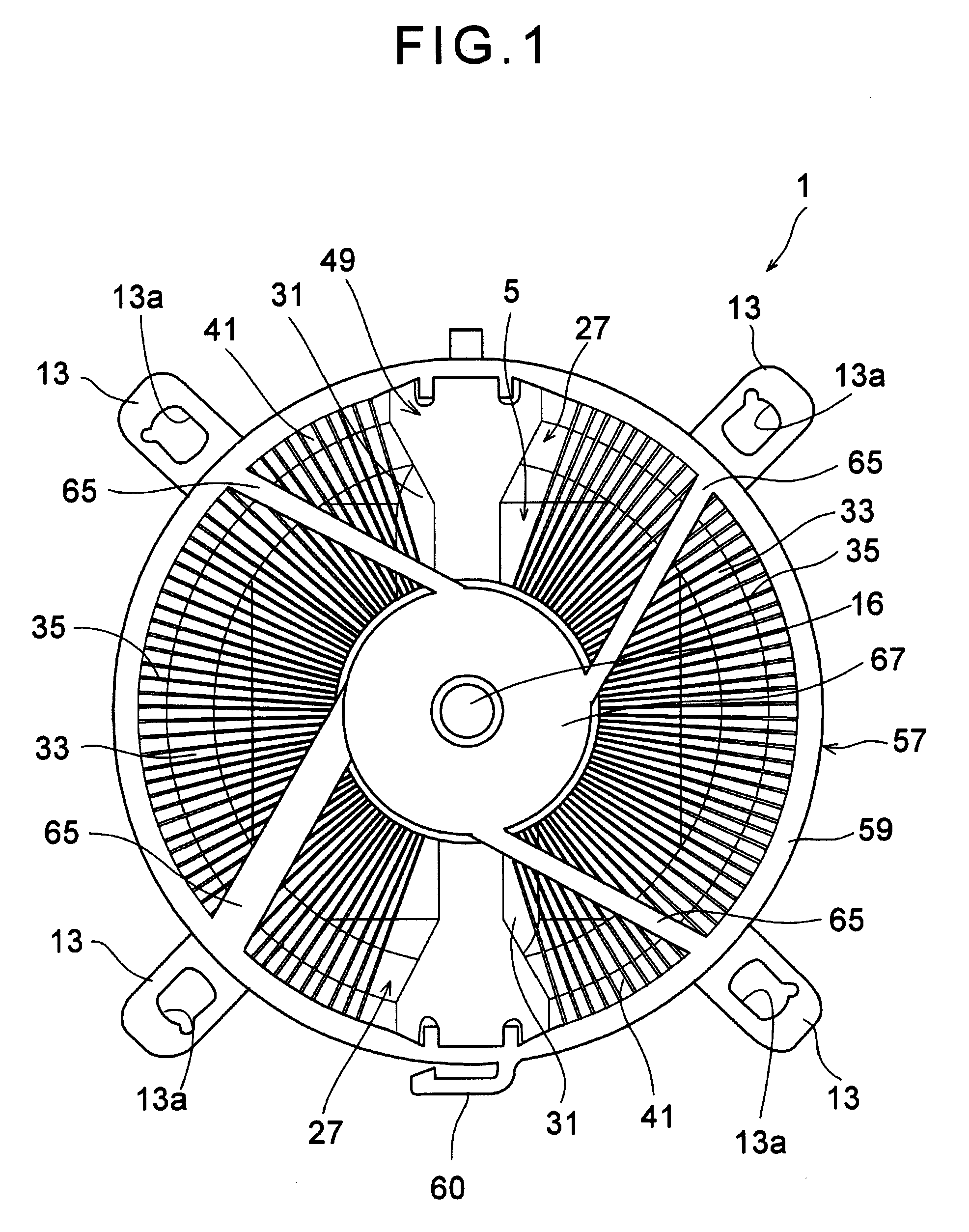
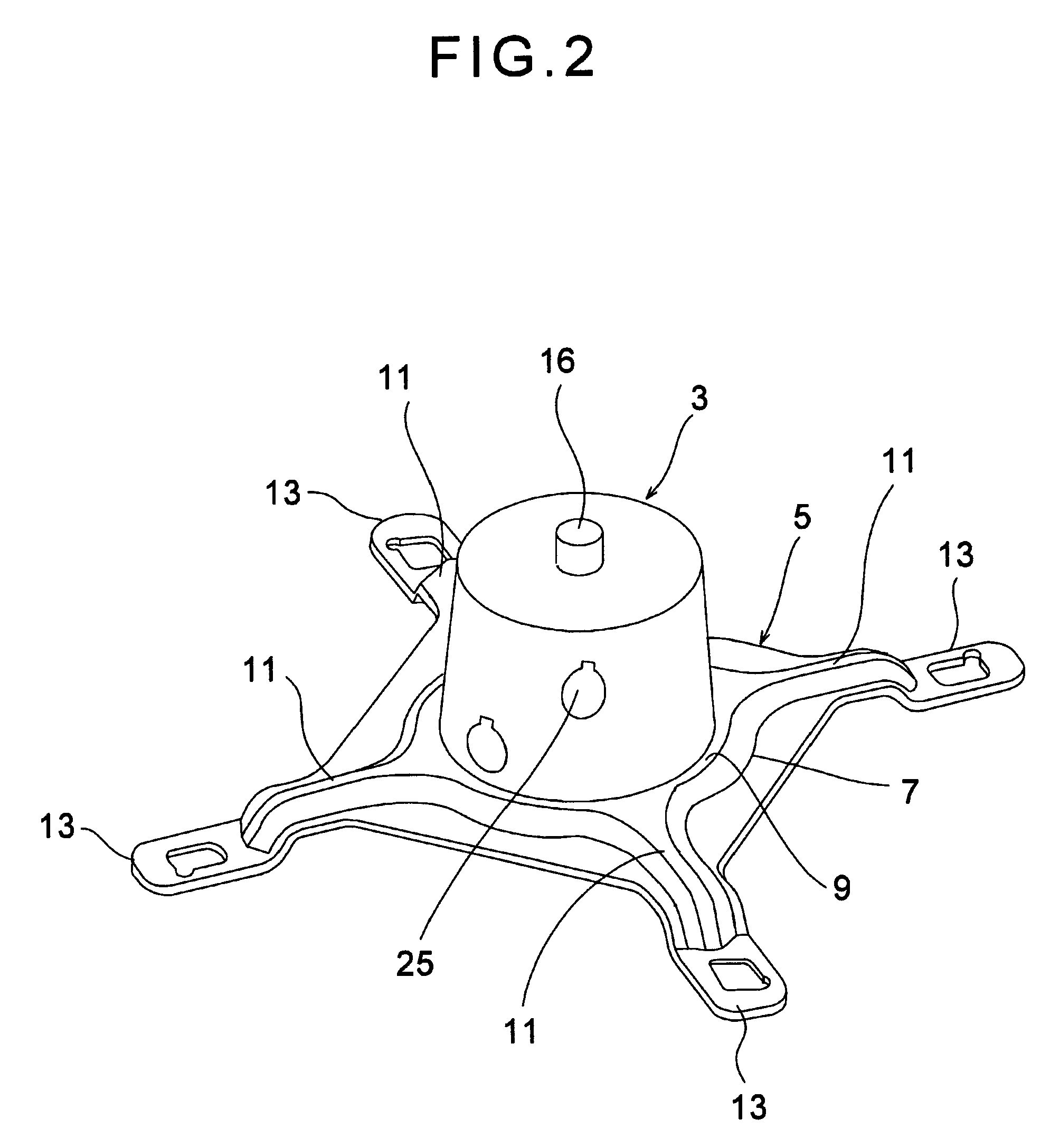
[0039]Here will be described a first exemplary embodiment of the invention. FIG. 1 is a top view showing a heat sink according to the invention. The heat sink 1 illustrated in FIG. 1 comprises an installation base 5. As illustrated in FIGS. 2 to 4, a heat receiving base 3 is mounted on a center of the installation base 5, and a bottom face of the heat receiving base 3 is aligned to be contacted with at least an upper face of a not-shown electron device as an exothermic element, e.g., a central processing unit.

[0040]As illustrated in FIG. 2, the installation base 5 comprises a base plate 7, a circular reinforcement frame 9, linear reinforcement frames 11 and clips 13. The circular reinforcement frame 9 is formed on the base plate 7 at a predetermined height, and the heat receiving base 3 is mounted thereon. The linear reinforcement frames 11 extend from the circular reinforcement frame 9 radially to four corners of the base plate 7, and the end portion thereof is bent downwardly. At ...

second embodiment

[0067]Next, a heat sink 71 as the present invention will be explained with reference to FIGS. 12 to 14. FIG. 12 is a top view showing the heat sink 71.

[0068]Differences between the heat sink 71 of the second embodiment and the heat sink 1 of the first embodiment are configurations of a heat receiving base 73, heat radiation fins 81 and heat pipes 85. The remaining elements of the heat sink 71 illustrated in FIGS. 12 to 14 are similar to those of the heat sink 1, so further description will be omitted by allotting common reference numerals.

[0069]The heat receiving base 73 is made of a material whose heat conductivity is excellent such as a copper. As illustrated in FIG. 13, the heat receiving base 73 comprises a column shaped heat receiving body 75, and a cylindrical heat exhausting portion 77 which is formed integrally on a circumference of the heat receiving body 75. In heat receiving body 75, there are formed two vertical holes 79 into which an evaporating side of the after mentio...

third embodiment

[0078]Differences between the heat sink 91 of the third embodiment and the heat sink 1 and 71 are configurations of a heat receiving base 93, heat radiation fins 99a to 99n and heat pipes 97. The remaining elements of the heat sink 91 illustrated in FIGS. 15 to 17 are similar to those of the heat sinks 1 and 71, so further description will be omitted by allotting common reference numerals.

[0079]The heat receiving base 93 is made of a material whose heat conductivity is excellent such as a copper. As illustrated in FIG. 16, the heat receiving base 93 also has a column-shaped main body, and comprises vertical holes 93 into which an evaporation side of the after mentioned heat pipes 97 are buried tightly. The heat receiving base 93 further comprises a plurality of protrusions 93b, which are formed around outer circumference at regular intervals, and to which heat radiating fins 99a are contacted.

[0080]As illustrated in FIGS. 15 and 16, the heat pipes 97 in which the evaporation side is...


PUM


Abstract

To improve a heat exchange efficiency of a heat sink without enlarging the heat sink. The heat sink of the invention comprises a heat receiving base receiving heat from an exothermic element, a plurality of fins radiating heat arranged radially around the heat receiving base at predetermined intervals, and one or more heat pipe(s) comprising a curved portion. One of end portions of the curved portion is individually connected to a predetermined portion of the heat receiving base, and a predetermined region of the curved portion is contacted with the fins in a heat transferable manner.

Description

[0001]This application claims priority from Provisional Application Ser. No. 60 / 891,889, filed Feb. 27, 2007, pending, incorporated herein by reference.BACKGROUND OF THE INVENTION[0002]1. Field of the Invention[0003]The present invention deals with a heat sink for cooling an exothermic element using a heat pipe for transporting heat in the form of latent heat of a condensable working fluid encapsulated therein.[0004]2. Discussion of the Related Art[0005]A heat pipe is a generally known heat transfer device for transporting heat in the form of latent heat of a condensable working fluid. A non-condensable gas such as an air is evacuated from a container of the heat pipe, and a condensable fluid such as water or hydrocarbon is encapsulated therein. The container is sealed air-tightly. Therefore, if a part of the heat pipe is heated from outside when another part of the heat pipe is being cooled, the working fluid is vaporized by the heat, and the vapor flows toward a cooled part where ...

Claims


Application Information

Patent Timeline
Patent Type & Authority Applications(United States)
IPC IPC(8): F28D15/00
CPCF28D15/0233F28F1/32F28F3/02H01L23/427H01L23/467H01L2924/0002F28D15/0275H01L2924/00
Inventor MOCHIZUKI, MASATAKA
Owner THE FUJIKURA CABLE WORKS LTD
Why Eureka
Try Eureka