Control valve for a water tap
- Summary
- Abstract
- Description
- Claims
- Application Information
AI Technical Summary
Benefits of technology
Problems solved by technology
Method used
Image

Examples
first embodiment
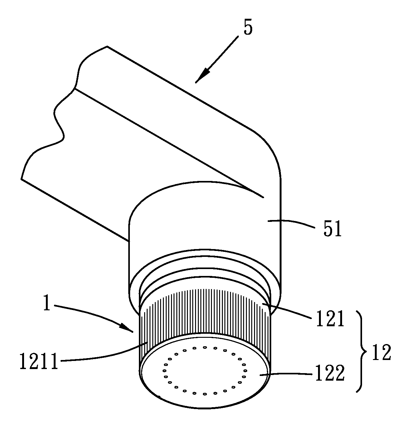
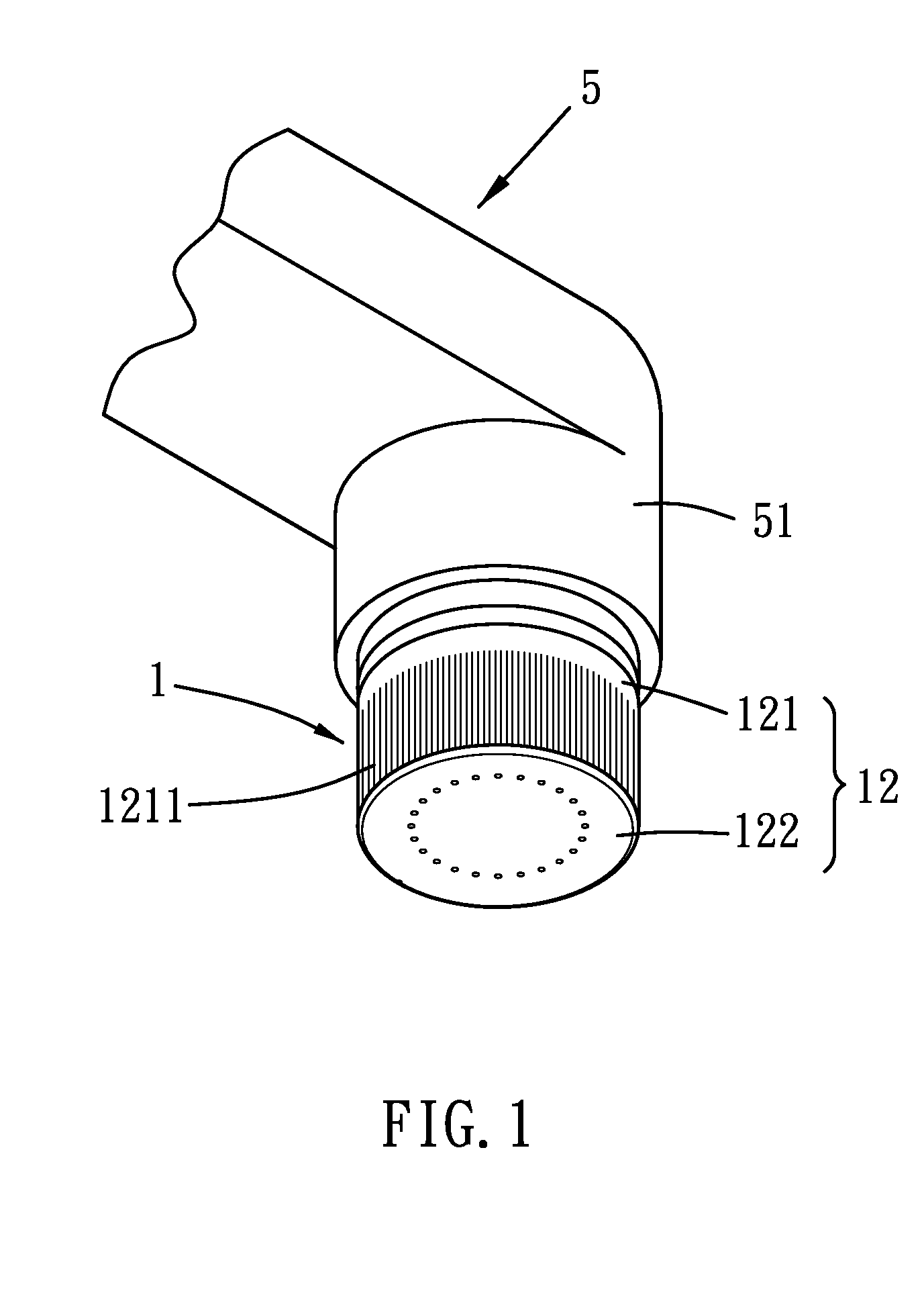
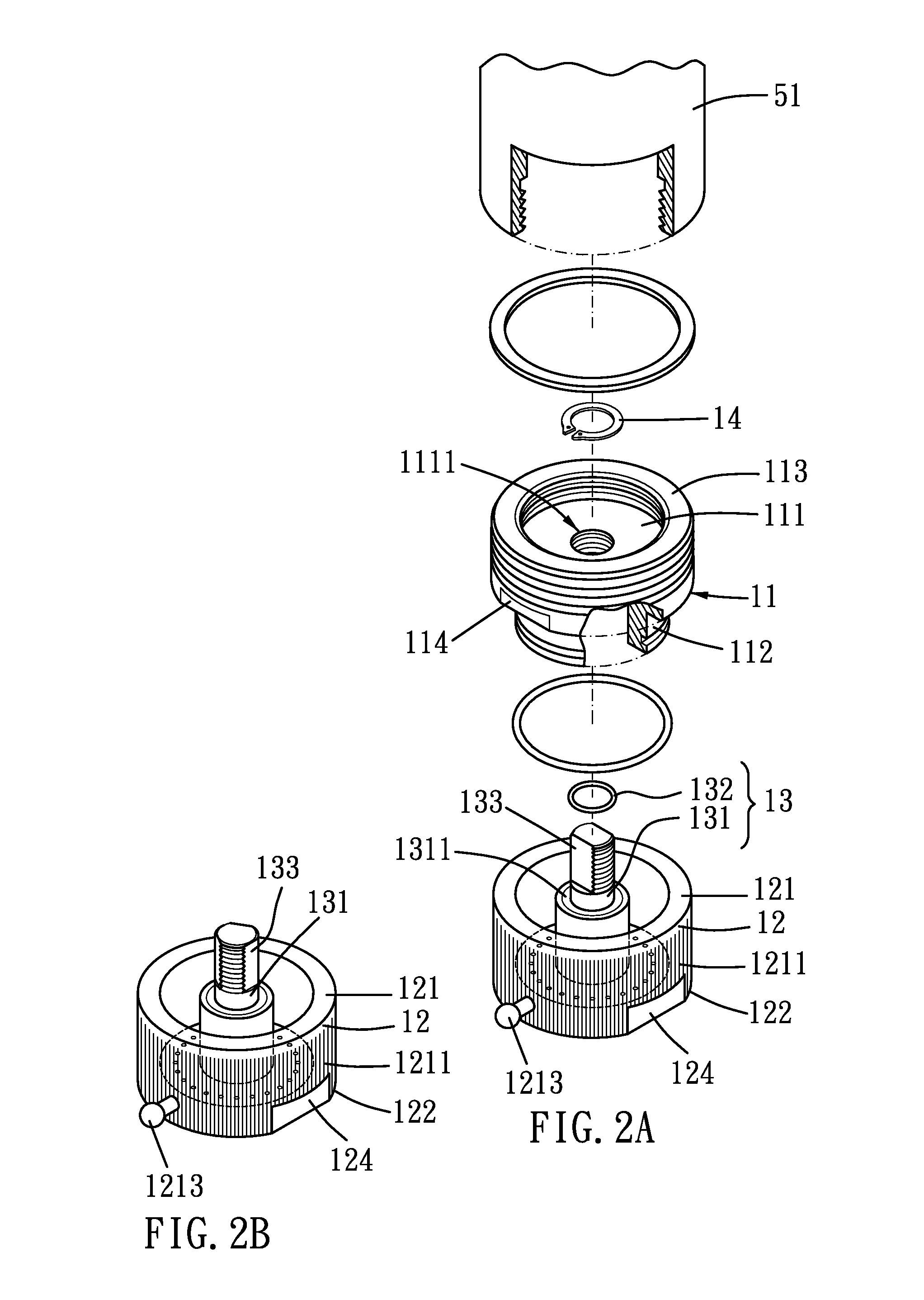
[0025]Referring to FIGS. 1 and 2A, a control valve 1 for a water tap in accordance with the present invention comprises a connecting member 11, a drain member 12 and a stop assembly 13, wherein the control valve 1 is disposed on an outlet connection 51 with internal thread of a water tap 5.
[0026]As shown in FIGS. 1, 2A, 3A and 3B, the connecting member 11 includes a stop groove 111, a small-diameter portion 112, and a large-diameter portion 113, wherein the stop groove 111 includes a through hole 1111 with internal thread mounted at the center thereof, and the small-diameter portion 112 extends downward in an axial direction from the bottom of the large-diameter portion 113. Besides, the large-diameter portion 113 is axially extended upward around the stop groove 111 and includes internal and external threads formed on the inner and outer walls respectively, such that the large-diameter portion 113 of the connecting member 11 is screwed with the outlet connection 51 of the water tap...
second embodiment
[0029]Referring further to FIGS. 2B and 3B and 3C, a control valve 1 for a water tap in accordance with the present invention comprises a stop assembly 13 having a two-stepped upright shaft 131 with large-diameter and small-diameter portions and a stop washer 132, wherein the upright shaft 131 is disposed at the center of the bottom 122 of the drain member 12. It is to be noted that the upright shaft 131 is integrally formed with the drain member 12 or separately assembled into the drain member 12 in a locking manner. Besides, on the upper end of the upright shaft 131 is arranged external thread to screw the upright shaft 131 with the through hole 1111 of the connecting member 11, and the width of the small-diameter portion of the upright shaft 131 is less than that of the through hole 1111. The upright shaft 131 includes two spaced flat planes 133 fixed on the upper end thereof and axially extending along its external thread such that the external thread around the upper end of sma...
third embodiment
[0033]It is to be noted that the retaining portion 214 may also be formed in other shapes. For example, as shown in FIGS. 6A and 6B, a retaining portion 314 of a control valve 3 according to the present invention is formed in a funnel shape, and the shape of a protrusion 3311 of an upright shaft 331 is in response to that of the retaining portion 314. Moreover, a stop washer 332 is defined between the protrusion 3311 and the retaining portion 314 so as to seal the protrusion 3311 and the retaining portion 314.
[0034]With reference to in FIG. 7, a control valve 1 for a water tap in accordance with a first embodiment of the present invention further comprises a water saver 15 screwed with the drain member 12 and including a spout 151 arranged on the bottom thereof. The passage 123, the outlets 1221, and the spout 151 are in communication with each other, such that the water and air can be mixed well to decrease the strong water spray, obtaining a water saving purpose.
PUM
 Abstract
Description
Claims
Application Information
 - Generate Ideas
- Intellectual Property
- Life Sciences
- Materials
- Tech Scout
- Unparalleled Data Quality
- Higher Quality Content
- 60% Fewer Hallucinations
Browse by: Latest US Patents, China's latest patents, Technical Efficacy Thesaurus, Application Domain, Technology Topic, Popular Technical Reports.
© 2025 PatSnap. All rights reserved.Legal|Privacy policy|Modern Slavery Act Transparency Statement|Sitemap|About US| Contact US: help@patsnap.com