
Magnetic method and apparatus for increasing foot traction on sports boards

a technology of magnetic method and foot traction, applied in the field of sports boards, can solve the problems of user feet being fixed and its practical utility almost entirely restricted, and achieve the effect of enhanced footing and traction

Inactive Publication Date: 2010-02-04
FLAIG THEODORE J
View PDF11 Cites 12 Cited by
  • Summary
  • Abstract
  • Description
  • Claims
  • Application Information

AI Technical Summary

Benefits of technology

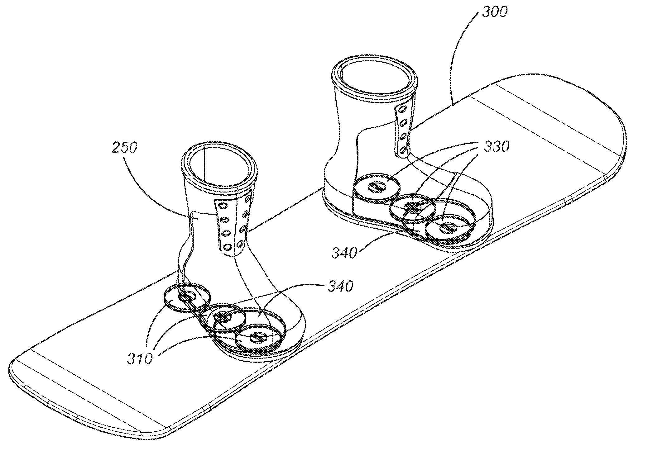
[0016]In a first preferred embodiment, the present invention is a magnetic sports board binding and foot traction apparatus. In its most essential aspect, the inventive apparatus comprises one or more magnet holding receptacles disposed in or slightly below either the upper surface (on which a user stands) or lower (ground-facing or water-facing surface) of a sports board, each receptacle having a ferromagnetic bar disposed in or under at least a portion of the bottom of the receptacle. Permanent magnets are selectively placed into the one or more receptacles and each bind to the ferromagnetic bar, holding them firmly in place even during the most violent of sports activities. The insertion of the magnet(s) into the receptacles thus forms a magnetic region on the surface of the sports board. The sports board user is then provided with footwear having a ferromagnetic plate affixed to, or incorporated into, at least a portion of the sole of the footwear. Accordingly, when the user mounts the sports board and brings his or her foot into proximity with the magnetic region of the sports board, footing and traction are enhanced.
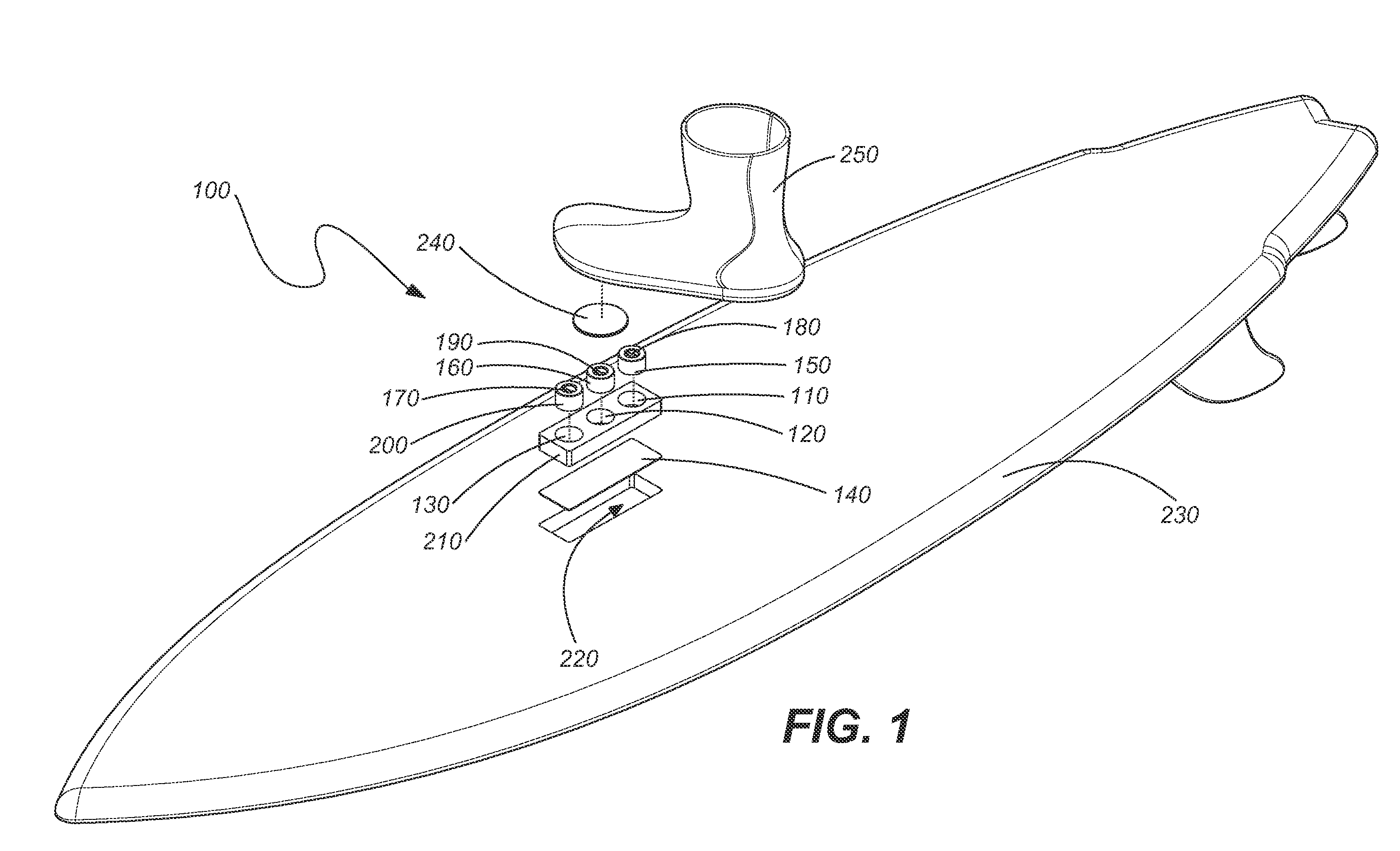
[0017]In the first preferred embodiment, the magnet holding receptacles are formed in a magnet holding box, preferably polycarbonate, which may be formed into the sports board at the time of manufacture or placed into a recess (or cutout) cut into the board for a retrofit installation. The magnet holding box provides magnet holding receptacles in an ordered array according to the kind of footwork anticipated during board use. In this embodiment, the permanent magnets are preferably cylindrical disks having finger or tool gripping means on their upper surfaces so that they can be easily lowered into and pulled out of the magnet holding receptacles. In this fashion, the magnetic region of the sports board can be precisely tailored to the wants and needs of the user by employing a very specific magnet or combination of magnets that create the desired holding power.
[0021]A further object or feature of the present invention is a new and improved sports board binding and foot traction apparatus that enables a rapid change in the binding force provided by the magnets so that different safety and / or performance requirements can be addressed.
[0022]An even further object of the present invention is to provide a novel sports board binding and foot traction apparatus that can be selectively used or eliminated entirely when so desired by the user.
[0023]Yet another object of the present invention is to provide attractive and functional sports board footwear having magnets incorporated into the footwear sole and thus suitable for use in a magnetic sports board binding system of the kind described herein.

Problems solved by technology

As a first instance of magnetic binding methods, the cleverness of the '383 patent is undeniable, but its practical utility is almost entirely restricted to use on skis, as the binding units are bulky, fixed, and work only with relative rigid boots.
While this system allows for selective placement of the user's feet on the sports board, it entails the use of rigid boots and so is truly suitable only for snow boards, but not for skateboards, surfboards, wakeboards, and other sports boards used with free feet.
The limitation of this method is that the user's feet are fixed at the position of the knobs.

Method used


Image

  • Magnetic method and apparatus for increasing foot traction on sports boards
  • Magnetic method and apparatus for increasing foot traction on sports boards
  • Magnetic method and apparatus for increasing foot traction on sports boards

Examples


Embodiment Construction

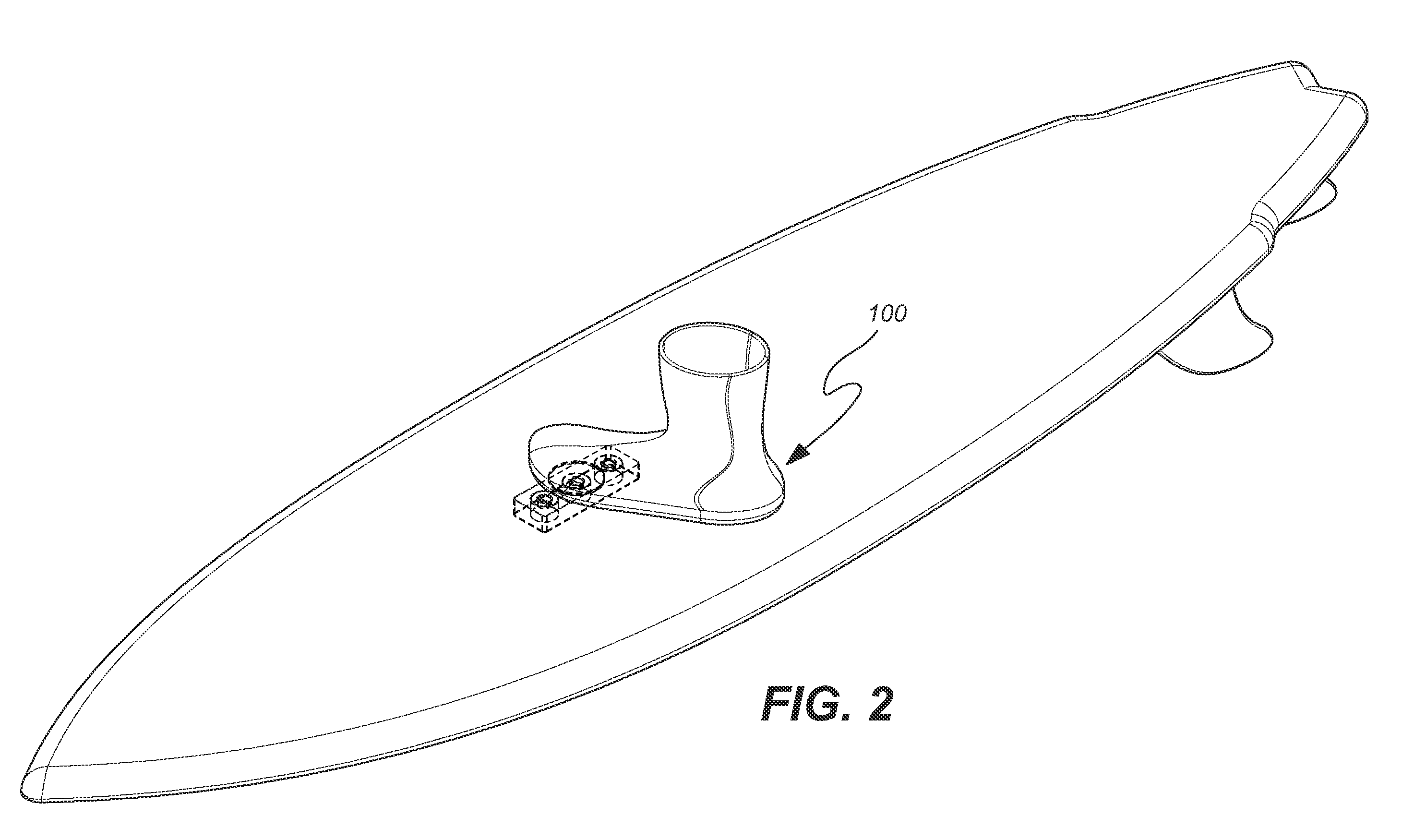
[0045]Referring to FIGS. 1 through 14B, wherein like reference numerals refer to like components in the various views, there is illustrated therein a new and improved magnetic sports board binding foot traction apparatus, generally denominated 100 herein.

[0046]FIGS. 1 and 2 show a first preferred embodiment of the inventive apparatus as employed for use in a surfboard. These views show that in a first preferred embodiment the binding and foot traction of the present invention comprises one or more magnet holding receptacles 110, 120, 130, disposed in a magnet holding box 210 for placement in a recess 220 in the deck or top side of a sports board, in this instance a surfboard. The receptacles may be arranged in a linear array or in any other arrangement suited to the kind of footwork anticipated by the user or common to the sport. The receptacles are open at the top before insertion of magnets and preferably remain open and after insertion. At least a portion of the base or bottom of...


PUM


Abstract

A sports board binding and foot traction apparatus for use in sports boards such as surfboard, skateboard, wakeboards, and the like. The apparatus includes a sports board having a deck and a bottom and at least one cutout box disposed in one or both of the deck and bottom. One or more permanent magnets is disposed and retained in one or more of the cutout boxes to form a magnetic region on the deck of the board. An article of sports footwear having a sole is provided, and a ferromagnetic plate is disposed in at lest a portion of each footwear sole. When the footwear is brought into proximity with the magnetic field, a binding force is applied to the footwear and the wearer is thereby enabled to manipulate the sports board in ways not possible without the inventive apparatus.

Description

CROSS REFERENCES TO RELATED APPLICATIONS[0001]The present application is a continuation-in-part of U.S. patent application Ser. No. 11 / 370,348, now U.S. Pat. No. 7,338,067, issued Mar. 4, 2008 (Mar. 4, 2008), and a continuation-in-part of U.S. patent application Ser. No. 12 / 041,579, filed Mar. 3, 2008 (Mar. 3, 2008).SEQUENCE LISTING[0002]Not applicable.STATEMENT REGARDING FEDERALLY SPONSORED RESEARCH OR DEVELOPMENT[0003]Not applicable.THE NAMES OR PARTIES TO A JOINT RESEARCH AGREEMENT[0004]Not applicable.INCORPORATION-BY-REFERENCE OF MATERIAL SUBMITTED ON A COMPACT DISC[0005]Not applicable.BACKGROUND OF THE INVENTION[0006]1. Field of the Invention[0007]The present invention relates generally to sports boards, such as skateboard, surfboards, snowboards, windsurfing boards, kitesurfing boards, wakeboards, and the like, and more particularly to binding methods and methods of providing foot traction on such boards.[0008]2. Discussion of Related Art[0009]The 2006 Winter Olympics brought ...

Claims


Application Information

Patent Timeline
Patent Type & Authority Applications(United States)
IPC IPC(8): A63C9/00A43B5/00
CPCA63C5/128A63C10/10A63C10/12A63C10/18A63C5/03B63B35/79B63B35/7936B63B35/812B63B2231/30A63C10/20B63B32/47
Inventor FLAIG, THEODORE J.
Owner FLAIG THEODORE J
Learn More