Stationary induction apparatus fixing structure and fixing member

a technology of fixing structure and fixing member, which is applied in the direction of electrical apparatus, transformer/inductance details, inductance, etc., can solve the problems of increasing the amount of resin packed, the possibility of shifting or similar, and the increase of the number of components and assembly processes. achieve the effect of reliable fixing and easy assembly

Active Publication Date: 2010-02-04
TAMURA KK
View PDF17 Cites 34 Cited by
  • Summary
  • Abstract
  • Description
  • Claims
  • Application Information

AI Technical Summary

Benefits of technology

[0010]This invention is proposed in order to resolve the above-described problems of the technology of the prior art, and has as an object the provision of a fixing structure and a fixing member for a stationary induction apparatus which comprise a small number of components, are inexpensive and can be assembled easily, and which enable reliable fixation.

Problems solved by technology

However, in the above-described technologies of the prior art, the direction in which the core is fixed is a single direction, so that there is the possibility of shifting or similar in directions in which the core is not fixed.
However, these methods entail an increase in the number of components and an increase in the number of assembly processes.
However, because the leaf spring has a thin plate shape, there is a large amount of space within the case other than the leaf spring, and the amount of resin packed is increased.
Such an increase in the amount of packed resin results in increased manufacturing costs when the resin is comparatively expensive (as in the case of urethane resins, for example).
In particular, when using a design in which there is pressing from above by a retainer as in Patent Document 2, there is still more space within the case, and costs are increased.
Hence when using a laminated core or similar, manufactured by laminating silicon steel sheets or other materials, there is the possibility of local concentration of excessive force along the lamination direction.

Method used


Image

  • Stationary induction apparatus fixing structure and fixing member
  • Stationary induction apparatus fixing structure and fixing member
  • Stationary induction apparatus fixing structure and fixing member

Examples


Embodiment Construction

[0051]Next, aspects of the invention (hereafter simply “aspects”) are explained in detail, referring to the drawings.

[0052](Overall Configuration of Reactor: FIG. 1 Through FIG. 4)

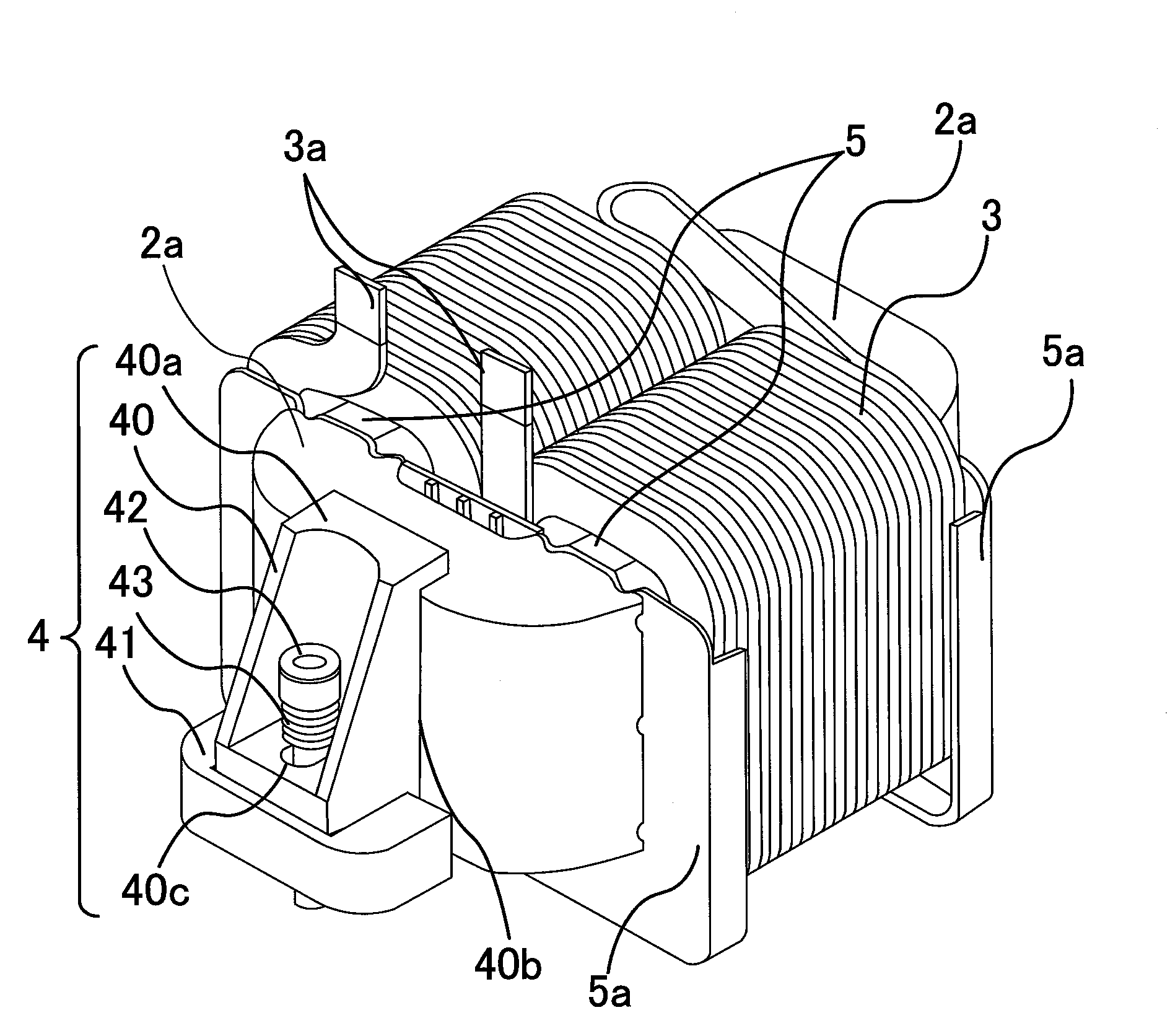
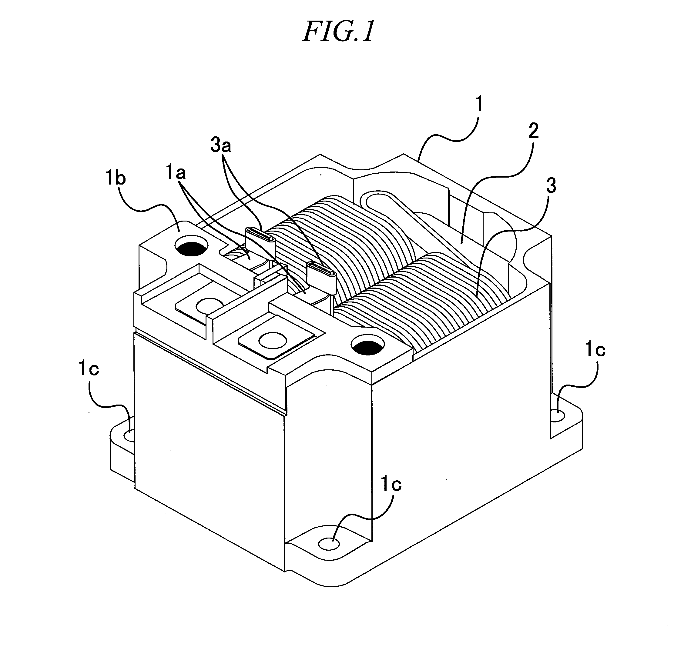
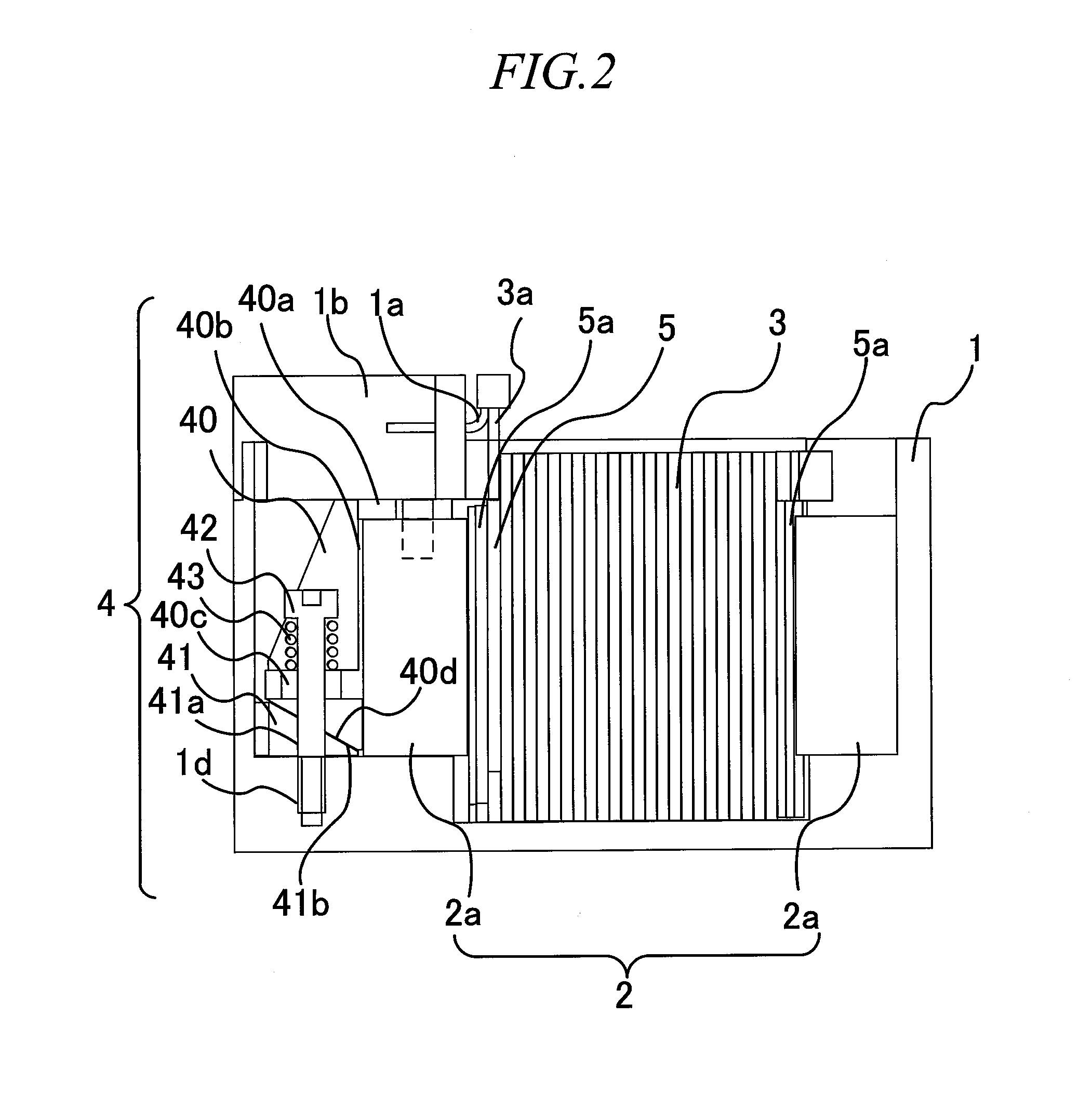
[0053]First, the configuration of an aspect is explained referring to FIG. 1 through FIG. 4. FIG. 1 is an external perspective view of a reactor to which this aspect is applied, FIG. 2 is a cross-sectional view, FIG. 3 is a perspective view showing the internal structure, and FIG. 4 is an exploded perspective view of the fixing portion.

[0054]That is, as shown in FIG. 1, the reactor to which this aspect is applied is formed by housing a core 2 and coil 3 within a case 1. As shown in FIG. 2 through FIG. 4, the core 2 within the case 1 is fixed by the fixing portion 4. And, the interior of the case 1 is packed with a urethane or other resin (not shown) such that the end portion 3a of the coil 3 is exposed.

[0055](Case Configuration: FIG. 1 and FIG. 2)

[0056]The case 1 is an aluminum alloy housing, the upper por...


PUM

PropertyMeasurementUnit
impelling forceaaaaaaaaaa
structuresaaaaaaaaaa
shapeaaaaaaaaaa

Abstract

The present invention provides a fixing structure and a fixing member for a stationary induction apparatus, which can easily and inexpensively be assembled with a small number of constituent elements, and which are capable of reliable fixation. A fixing portion 4 which fixes the core 2 of a reactor to a case 1 is provided. The fixing portion 4 has a slide block 40 in contact with the core 2; a fixing bolt 42 which fixes the slide block 40 with respect to the case 1; and a slide base 41 provided between the slide block 40 and the case 1, and fixed to the case 1 together with the slide block 40. The slide block 40 and the slide base 41 have inclined faces 40d, 41b in mutual contact, and the slide block 40 has a first impelling portion 40a which impels the core 2 in a vertical direction and a second impelling portion 40b which impels the core 2 in a horizontal direction, according to fastening by the fixing bolt 42.

Description

TECHNICAL FIELD[0001]This invention relates to a fixing structure to fix a stationary induction apparatus such as, for example, a reactor on a support member, and in particular relates to a stationary induction apparatus fixing structure and fixing member with improvement in the impelling direction for fixation.BACKGROUND ART[0002]Various stationary induction apparatuses, such as reactors, voltage transformers, current transformers, and similar, comprising a coil and a core, are in use today. For example, reactors are connected to step-up circuits, inverter circuits, active filter circuits, and various other electrical circuits, in which the inductive reactance is used; reactors with various structures have been developed for diverse applications. Many reactors have a coil and core are housed within a metal case with other insulating members or similar, in a structure which is packed with resin.[0003]When a reactor housing a core and coil in a case is to be packed with resin, the co...

Claims


Application Information

Patent Timeline
Patent Type & Authority Applications(United States)
IPC IPC(8): H01F27/06
CPCH01F27/06H01F2038/305H01F30/16H01F27/266
Inventor OKAMOTO, TADAYUKIMAENO, KENSUKE
Owner TAMURA KK
Why Eureka
Try Eureka