
Liquid crystal display device

a display device and liquid crystal technology, applied in the field of liquid crystal display devices, can solve the problems of reducing productivity, increasing costs, and affecting the brightness of the lcd panel, and achieve the effects of enhancing display quality, high-speed operation of the sensor, and sufficient charge tim

Active Publication Date: 2010-02-04
LG DISPLAY CO LTD
View PDF2 Cites 52 Cited by
  • Summary
  • Abstract
  • Description
  • Claims
  • Application Information

AI Technical Summary

Benefits of technology

[0017]Another object of the present invention is to provide a liquid crystal display device capable of providing a sufficient charge time for a liquid crystal cell.
[0018]Another object of the present invention is to provide a liquid crystal display device capable of providing a sufficient sensor access time for a liquid crystal cell.
[0020]An object of the present invention is to enhance a display quality in a liquid crystal display device.
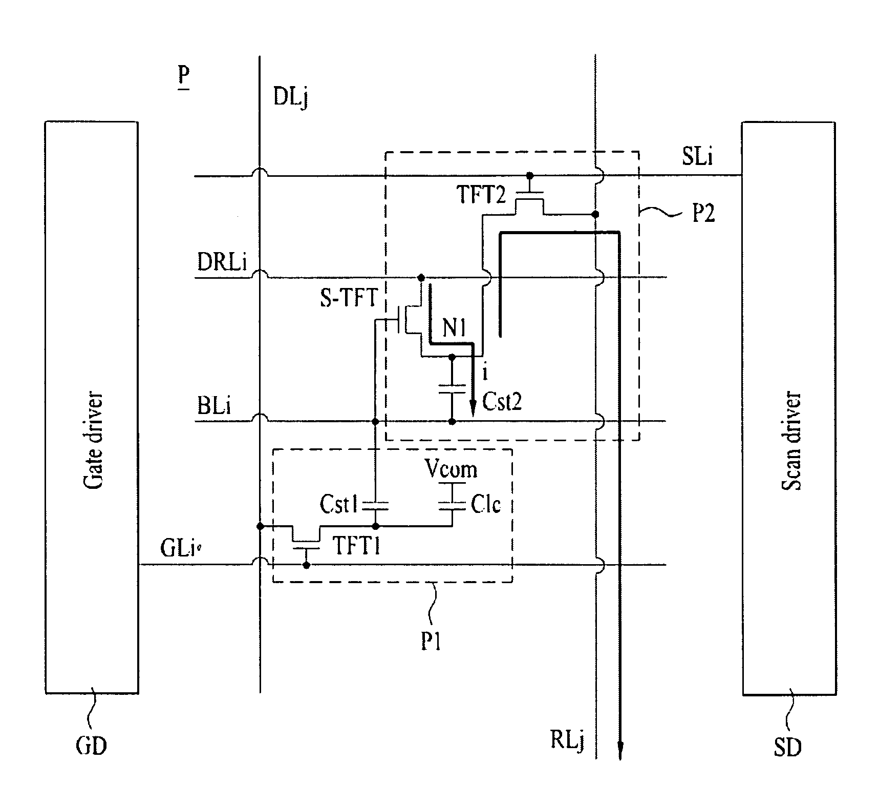
[0027]In accordance with the present invention, the pixel circuit and the touch sensor circuit are independently driven by different lines. Accordingly, it is possible to secure a sufficient charge time and a sufficient sensor access time for each liquid crystal cell, thereby achieving an enhancement in display quality and a high-speed operation of the sensor.
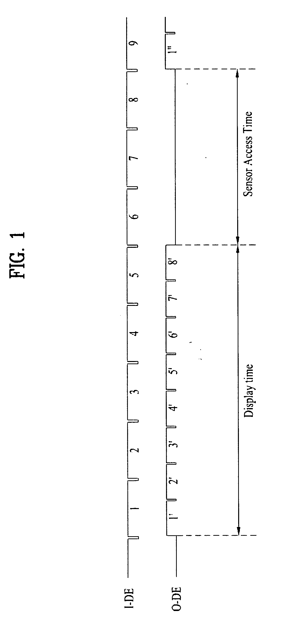
[0028]Also, it is possible to use a data enable signal input from a system, as it is, without a modulation thereof. Accordingly, it is unnecessary to use a separate memory for storing image data, and thus to reduce the manufacture costs.

Problems solved by technology

However, such an LCD device has various problems such as an increase in costs caused by the touch screen panel, a reduction in productivity caused by an addition of a process for attaching the touch screen panel to an LCD panel, and a degradation in the brightness of the LCD panel, and an increase in the thickness of the LCD panel.
Accordingly, the related art in-cell touch panel type LCD device may not be able to simultaneously display an image through the pixel circuit and;read the light sensing signal through the touch sensor circuit.
In the above-mentioned related art case, however, there is a problem in that an increase in manufacture costs occurs because it is necessary to use the memory for storing image data, in order to generate the second data enable signal O-DE.
As a result, degradation in display quality occurs.

Method used


Image

  • Liquid crystal display device
  • Liquid crystal display device
  • Liquid crystal display device

Examples


Embodiment Construction

[0036]Reference will now be made in detail to preferred embodiments of the present invention, examples of which are illustrated in the accompanying drawings. Wherever possible, the same reference numbers will be used throughout the drawings to refer to the same or like parts.

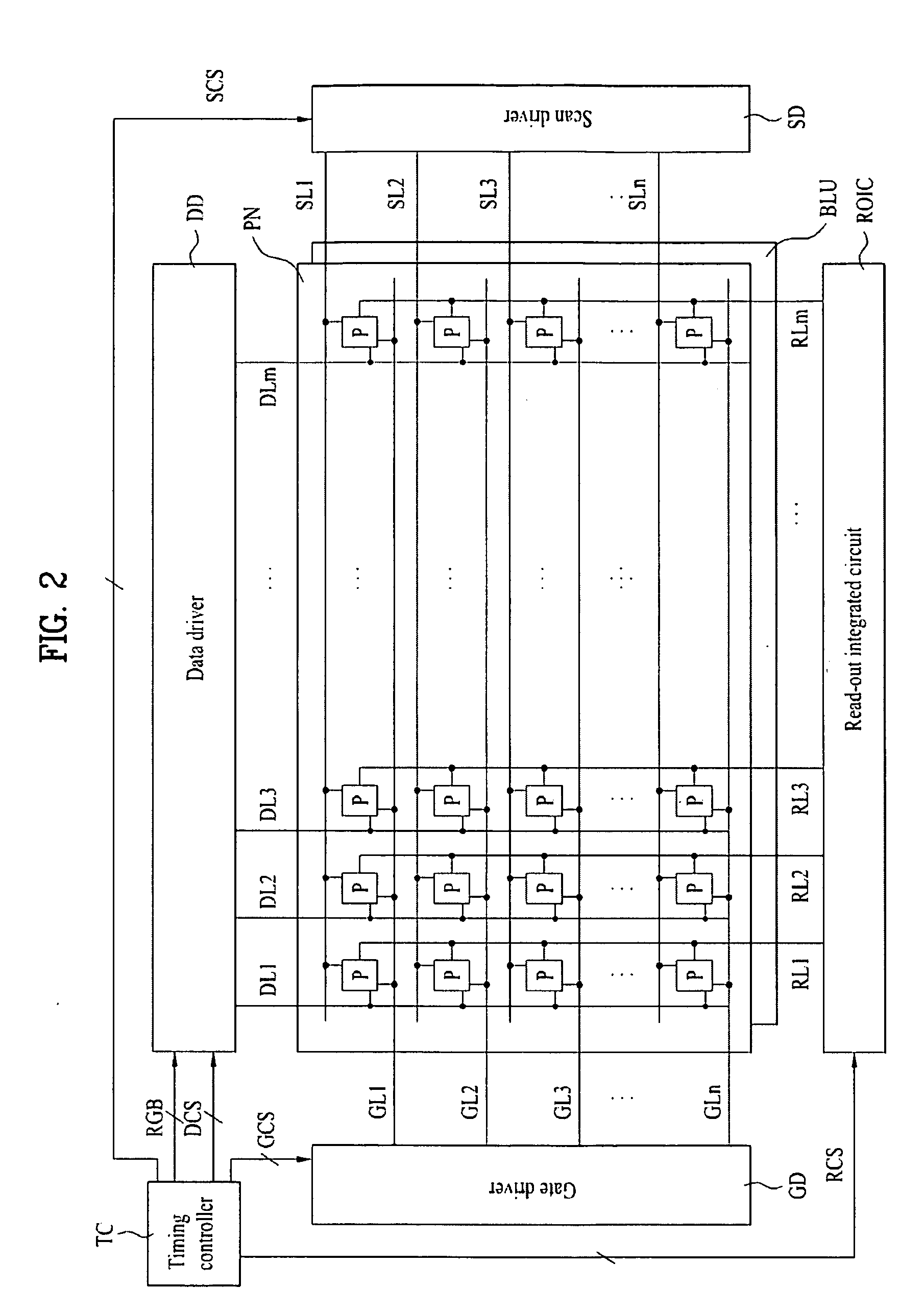
[0037]FIG. 2 is a block diagram illustrating a liquid crystal display (LCD) device according to an exemplary embodiment of the present invention. Referring to FIG. 2, the LCD device includes an LCD panel PN including a plurality of pixel cells P respectively at pixel regions defined by crossing of a plurality of gate lines GL1 to GLn, a plurality of scan lines SL1 to SLn, a plurality of data lines DL1 to DLm, and a plurality of read-out lines RL1 to RLm. The LCD device also includes a data driver DD for supplying a data voltage to the data lines DL1 to DLm, a gate driver GD for sequentially supplying a gate signal to the gate lines GL1 to GLn, and a scan driver SD for sequentially supplying a scan signal to the ...


PUM


Abstract

A liquid crystal display device having a plurality of pixel cells for displaying an image and sensing light incident on the pixel cells, each of the pixel cells includes a pixel circuit that displays an image based on a data voltage supplied from a data line in accordance with a gate signal from a gate line; and a touch sensor that senses light incident on the pixel cell, storing a light sensing signal based on the sensed light, and supplying the stored light sensing signal to a read-out integrated circuit via a read-out line in accordance with a scan signal from a scan line.

Description

[0001]This application claims the benefit of Korean Patent Application No. 10-2008-0076170 filed on Aug. 4, 2008, which is hereby incorporated by reference in its entirety.BACKGROUND OF THE INVENTION[0002]1. Field of the Invention[0003]The present invention relates to a liquid crystal display (LCD) device of an in-cell touch-panel type, and more particularly, to an LCD device capable of securing a sufficient charge time and a sufficient sensor access time for a liquid crystal cell.[0004]2. Discussion of the Related Art[0005]Typically, liquid crystal display (LCD) devices display an image by controlling the light transmittance of a liquid crystal layer, using an electric field applied to the liquid crystal layer in accordance with a video signal. Such an LCD device has advantages of compactness, thinness, and low power consumption. By virtue of such advantages, the LCD device is used for a portable computer such as a notebook PC, an office automation appliance, an audio / video applian...

Claims


Application Information

Patent Timeline
Patent Type & Authority Applications(United States)
IPC IPC(8): G06F3/041G09G3/36
CPCG02F1/13338G02F1/13624G02F1/136286G09G2310/06G09G3/3648G09G2300/0809G02F2001/13312G02F1/13312G06F3/0412
Inventor JANG, SU HYUKLEE, HWAN JOO
Owner LG DISPLAY CO LTD
Learn More