Microchip for forming emulsion and method for manufacturing the same

a microchip and emulsion technology, applied in the field of microchips, can solve the problems of difficult to form such a fine emulsion, the size of an emulsion particle is not constant, and the flow path is changed,

Active Publication Date: 2010-02-04
DAI NIPPON PRINTING CO LTD
View PDF5 Cites 21 Cited by
  • Summary
  • Abstract
  • Description
  • Claims
  • Application Information

AI Technical Summary

Benefits of technology

[0023]According to the present invention, the silicon substrate has formed therein the first fluid flow path (in which the first fluid flows), the second fluid flow path (in which the second fluid that is not mixed with the first fluid flows) and the emulsion formation flow path (in which an emulsion is formed). This configuration allows a fine emulsion composed of the first fluid and the second fluid (that is surrounded by the first fluid) to be formed in a stable manner.

Problems solved by technology

However, when a fluid flows in a flow path provided in a PDMS substrate at high pressure in order to form an emulsion, the fluid pressure may cause transformation of the flow path and an increase in the width of the flow path.
It is, therefore, difficult to form such a fine emulsion as described above using a microchip having the PDMS substrate.
However, there is a problem that the size of an emulsion particle is not constant.

Method used


Image

  • Microchip for forming emulsion and method for manufacturing the same
  • Microchip for forming emulsion and method for manufacturing the same
  • Microchip for forming emulsion and method for manufacturing the same

Examples


first embodiment

[0038]The first embodiment of the present invention is described below with reference to the accompanying drawings.

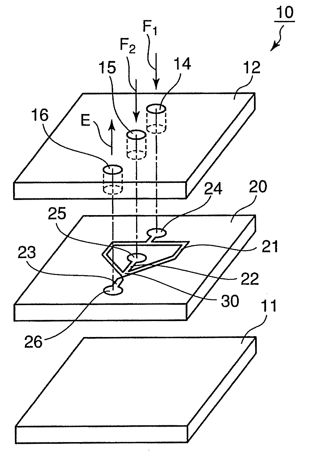
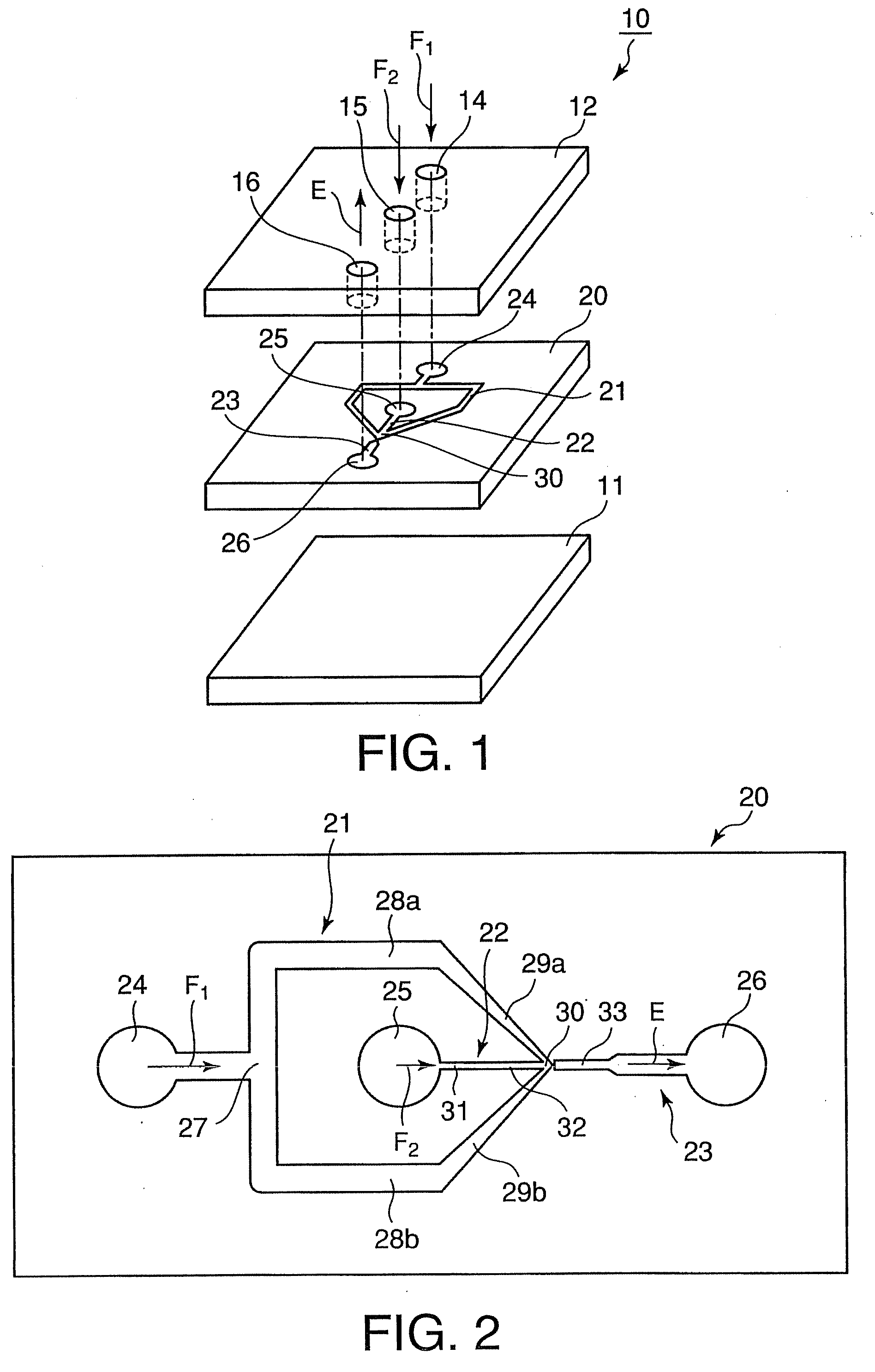
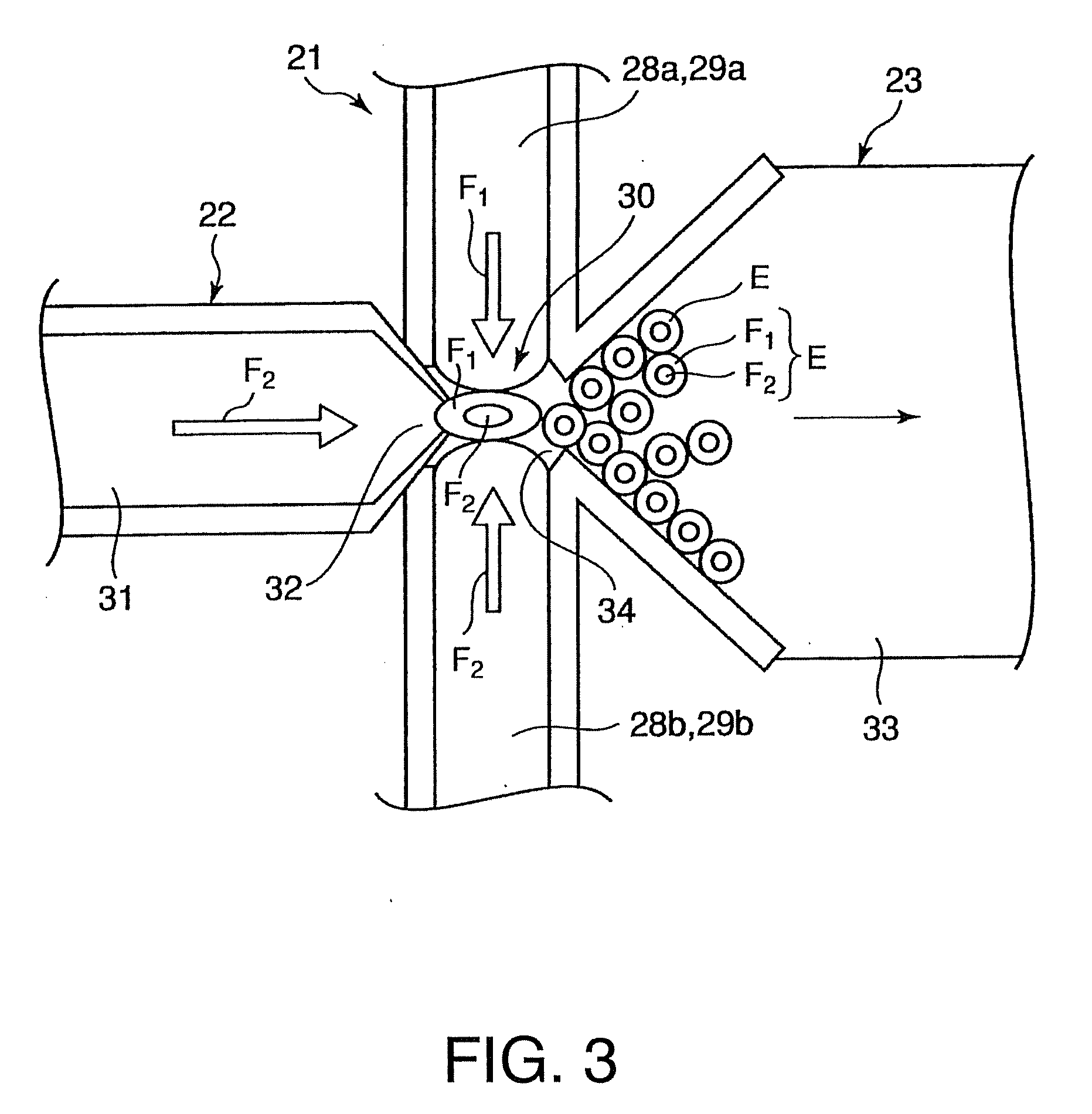
[0039]FIG. 1 is an exploded perspective view of a microchip for forming an emulsion according to the first embodiment. FIG. 2 is a plan view of a silicon substrate included in the microchip for forming an emulsion according to the first embodiment. FIG. 3 is an outline enlarged view of the periphery of a junction portion of the silicon substrate included in the microchip for forming an emulsion according to the first embodiment. FIG. 4 is a perspective view of the periphery of a restricting portion of the silicon substrate included in the microchip for forming an emulsion according to the first embodiment when viewed from an emulsion formation flow path. FIG. 5 is a vertical cross-sectional view of the restricting portion of the silicon substrate included in the microchip for forming an emulsion according to the first embodiment. FIGS. 6(a) to 6(f) are diagrams showing ...

second embodiment

[0082]The second embodiment of the present invention is described below with reference to FIGS. 6(a) to 6(c), 7, 8, 9(a) to 9(e), and 13(a) to 13(d). FIG. 7 is a perspective view of the periphery of a restricting portion of a silicon substrate included in a microchip for forming an emulsion according to the second embodiment of the present invention when viewed from an emulsion formation flow path. FIG. 8 is a vertical cross-sectional view of the restricting portion of the silicon substrate included in the microchip for forming an emulsion according to the second embodiment. FIGS. 9(a) to 9(e) are diagrams showing a method for manufacturing the microchip for forming an emulsion according to the second embodiment. FIGS. 13(a) to 13(d) are diagrams showing a modification of a process for forming flow paths by etching in the method for manufacturing the microchip forming an emulsion according to the present embodiment. The restricting portion according to the second embodiment shown in...

third embodiment

[0100]A method for manufacturing a microchip according to the third embodiment of the present invention is described below with reference to FIGS. 6(a) to 6(c), 9(a) to 9(d), 10, 11, 12(a), 12(b), and 13(a) to 13(d). FIG. 10 is a perspective view of the periphery of a restricting portion of a silicon substrate included in the microchip for forming an emulsion according to the present embodiment when viewed from an emulsion formation flow path FIG. 11 is a vertical cross-sectional view of the restricting portion of the silicon substrate included in the microchip for forming an emulsion according to the present embodiment. FIGS. 6(a) to 6(c), 9(a) to 9(d), 12(a) and 12(b) are diagrams showing the method for manufacturing the microchip for forming an emulsion according to the present embodiment. The restricting portion according to the third embodiment shown in FIGS. 6(a) to 6(c), 9(a) to 9(d), 10, 11, 12(a), 12(b), 13(a) to 13(d) is different from the restricting portion according to ...


PUM

PropertyMeasurementUnit
sizeaaaaaaaaaa
sizeaaaaaaaaaa
width w1aaaaaaaaaa

Abstract

A microchip for forming an emulsion has a first glass substrate, a second glass substrate and a silicon substrate. The silicon substrate has formed therein a first fluid flow path through which a first fluid flows and a second fluid flow path through which a second fluid that is not mixed with the first fluid flows. The first fluid flow path has a plurality of branched flow paths that join at a joint portion. The second fluid flow path communicates with the joint portion. The silicon substrate has formed therein an emulsion formation flow path that faces an edge portion of the second fluid flow path at the joint portion. An emulsion composed of the first fluid and the second fluid that is surrounded by the first fluid is formed in the emulsion formation flow path.

Description

CROSS REFERENCE TO RELATED APPLICATION[0001]The present application benefits from Japanese application serial number JP2008-194919, filed on Jul. 29, 2008, the entire content of which is hereby incorporated by reference into this application.BACKGROUND OF THE INVENTION[0002]1. Field of the Invention[0003]The present invention relates to a microchip that is adapted to form an emulsion and has first and second glass substrates and a silicon substrate provided between the first and second glass substrates, and to a method for manufacturing the microchip for forming an emulsion.[0004]2. Background Art[0005]In recent years, research has been carried out on cell analysis, chemical reaction, biochemical reaction, biochemical separation, biochemical analysis, etc. using a microchip called a micro total analysis system (μ-TAS), a microchip called a lab-on-a-chip, or a microchip called a micro electro mechanical system (MEMS). Such a microchip includes a plate having sides of several centimet...

Claims


Application Information

Patent Timeline
Patent Type & Authority Applications(United States)
IPC IPC(8): B01F13/00B01F5/06B32B37/12B01F25/46
CPCB01F3/0807B01F13/0062B01F5/0653B01F5/0646Y10T137/87652B01F23/41B01F25/4336B01F25/433B01F33/3011
Inventor OZAWA, YUTAKAOHIGASHI, RYOICHIFUJIMOTO, KOJITAKEUCHI, SHOJI
Owner DAI NIPPON PRINTING CO LTD
Why Eureka
Try Eureka