Optical information recording device, optical pickup, and method for emitting laser light
a laser light and optical pickup technology, applied in the field of optical information recording devices, optical pickups, laser light emitting methods, etc., can solve the problems of increasing the emission intensity of semiconductor lasers, reducing the efficiency of laser beams, and large cost of short pulse output light sources
- Summary
- Abstract
- Description
- Claims
- Application Information
AI Technical Summary
Benefits of technology
Problems solved by technology
Method used
Image

Examples
first embodiment
(1) First Embodiment
(1-1) Structure of Optical Disc
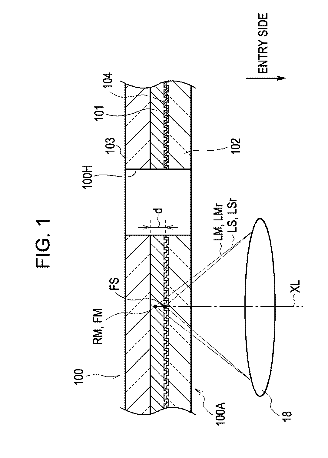
[0038]First, a structure of an optical disc is described. In the present embodiment, information is recorded on an optical disc 100 by irradiating the optical disc 100 with an information light beam LM that is emitted from an optical disc device 10. On the other hand, information is read from the optical disc 100 by detecting a reflected information light beam LMr that is a reflection of the information light beam LM.
[0039]The optical disc 100 is a substantially circular plate having a chucking hole 100H at the center thereof. As shown in a sectional view of FIG. 1, the optical disc 100 includes a recording layer 101 for recording information and substrates 102 and 103 sandwiching the recording layer 101.
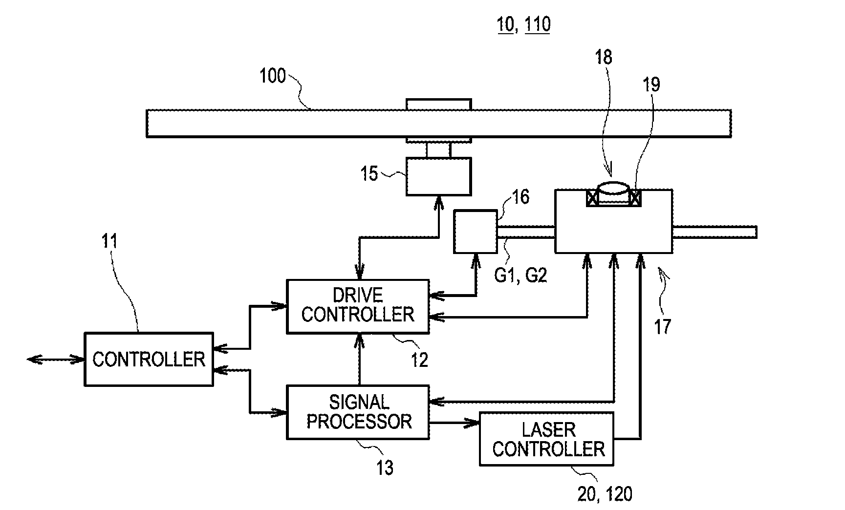
[0040]The optical disc device 10 collects the information light beam LM, which has been emitted by a light source, with an objective lens 18 into the recording layer 101 of the optical disc 100. When the information light beam LM ha...
second embodiment
(2) Second Embodiment
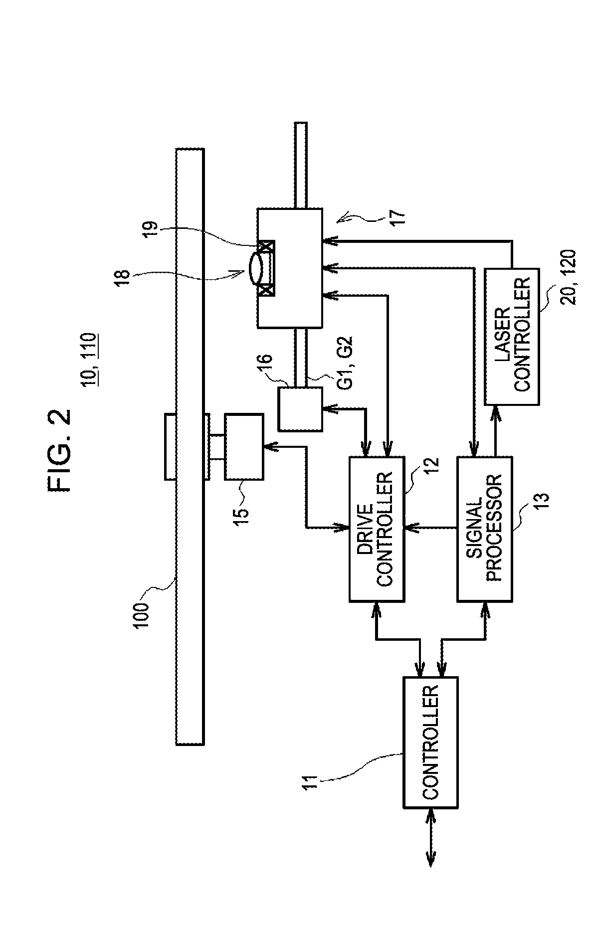
[0155]FIGS. 17 to 19 show a second embodiment. The same numerals are used for portions that correspond to the portions of a first embodiment shown in FIGS. 1 to 16. An optical disc device 110 of the second embodiment is different from the first embodiment in the method for generating the laser drive current DJ. The description of the optical disc device 110 (FIG. 2) is omitted because the structure of the optical disc device 110 is the same as that of the optical disc device 10.
(2-1) Method for Generating Laser Drive Current
[0156]As shown in FIG. 17 corresponding to FIG. 13, even when the semiconductor laser 51 is supplied with the same oscillation current value α (α3), if the laser drive current DJ is stopped being supplied during the first wave of the relaxation oscillation (i.e., before a first oscillation period ta has passed after the emission start time τd), the emission intensity of the pulse laser output beam LMp is reduced. If the laser drive current DJ...
PUM
 Abstract
Description
Claims
Application Information
 - R&D
- Intellectual Property
- Life Sciences
- Materials
- Tech Scout
- Unparalleled Data Quality
- Higher Quality Content
- 60% Fewer Hallucinations
Browse by: Latest US Patents, China's latest patents, Technical Efficacy Thesaurus, Application Domain, Technology Topic, Popular Technical Reports.
© 2025 PatSnap. All rights reserved.Legal|Privacy policy|Modern Slavery Act Transparency Statement|Sitemap|About US| Contact US: help@patsnap.com