Biaxial wheel test assembly

a test assembly and wheel technology, applied in vehicle tyre testing, instruments, roads, etc., can solve the problems of introducing errors in test data, complex mathematical algorithms are necessary to estimate actual loads, and frictional and hysteresis losses occurring within the support structure between load cells and wheel-and-tire assemblies that are difficult or impossible to account,

Active Publication Date: 2010-02-11
LINK ENG
View PDF15 Cites 37 Cited by
  • Summary
  • Abstract
  • Description
  • Claims
  • Application Information

AI Technical Summary

Problems solved by technology

One particular disadvantage of the biaxial wheel testing apparatus disclosed in Leska, Sr. et al. is the load cells are located remotely from the wheel-and-tire assembly and measure the input loads as opposed to the actual loads experienced by the wheel-and-tire assembly itself.
Therefore, complex mathematical algorithms are necessary to estimate the actual loads experienced by the wheel-and-tire assembly.
Another disadvantage is frictional and hysteresis losses occurring within the support structure between the load cells and the wheel-and-tire assembly that are difficult or impossible to account for.
Such algorithms and losses can introduce errors in the test data and provide failure modes that are unrealistic relative to that observed during real-world vehicle testing or provide erroneous or non-repetitive wheel damage.
Additionally, the above-described biaxial wheel testing apparatuses are relatively large and bulky in order to provide the necessary movement of the wheel-and-tire assembly.
Further, hydraulic systems used to load the wheel-and-tire assembly against the rotating drum have inherent disadvantages in that supply and return lines must be routed for each hydraulic actuator.
With multiple hydraulic line connections, leaks are unavoidable.
Using the predetermined and fixed optimum camber angle does not compensate for real-time factors that influence the effective loading of the wheel-and-tire assembly and hence the damage experienced by the wheel-and-tire assembly such as: tire-to-drum friction; friction variation with temperature at the tire contact patch; wheel-and-tire geometry, size and stiffness; tire rubber formulation; tread design and wear; and tire debris within the rotating drum.
The main effect of this fixed, optimum tilt or camber angle method is a random and unquantifiable source of variation in the test results and an inability to test with significant statistical correlation using different biaxial wheel testing apparatuses.

Method used


Image

  • Biaxial wheel test assembly
  • Biaxial wheel test assembly
  • Biaxial wheel test assembly

Examples


Embodiment Construction

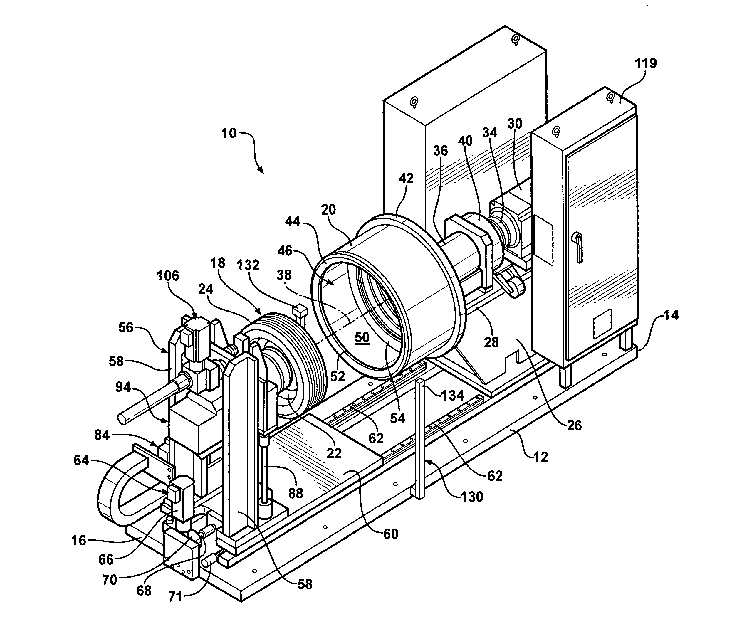
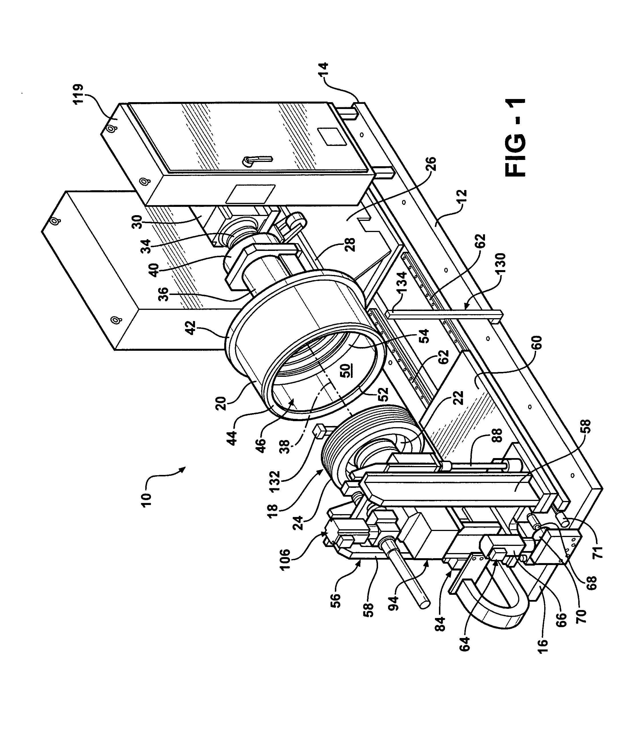
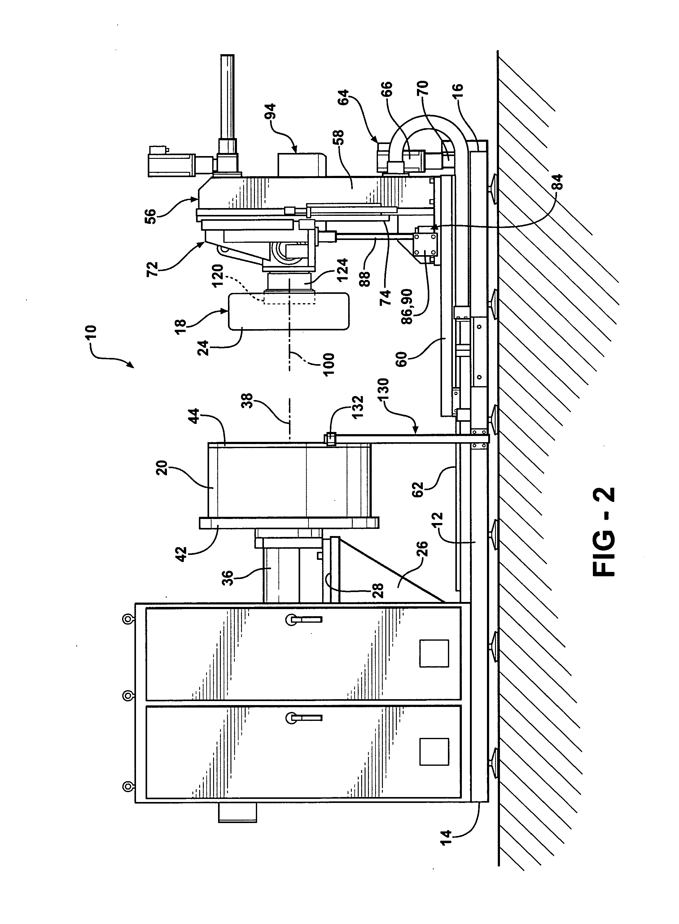
[0022]Referring to the Figures, FIGS. 1 and 2 disclose a biaxial wheel test assembly, generally shown at 10, that is provided for fatigue and durability testing of wheel components of a motor vehicle, such as, wheel rims, wheel hubs, wheel bearings, wheel bolts, and / or other braking, steering, and suspension components. The test assembly 10 is also provided for load versus strain mapping measurements of the above-listed wheel components. The test assembly 10 includes a primary base 12 or platform that extends between first 14 and second 16 ends and supports a wheel-and-tire assembly 18 in engagement with a rotating drum 20. The wheel-and-tire assembly 18 includes a wheel rim 22 with a tire 24 mounted to it.

[0023]A riser 26 is mounted to the first end 14 of the primary base 12 for rotatably supporting the drum 20 at a predetermined height above the primary base 12. The riser 26 includes an upper supporting surface 28 that is spaced apart from the primary base 12 in a vertical directi...


PUM


Abstract

A wheel test assembly for testing a wheel-and-tire assembly includes a drum operatively mounted to a base for rotation of the drum. The drum includes an inner circumferential surface. A tailstock assembly is slidably coupled to the base for movement in a lateral direction relative to the drum. A support assembly is slidably coupled to the tailstock assembly for movement in a vertical direction for positioning the wheel-and-tire assembly into rolling contact with the inner circumferential surface of the drum. A spindle assembly is pivotally coupled to the support assembly to adjust a camber angle of the wheel-and-tire assembly. The wheel-and-tire assembly is mounted to the spindle assembly for rotation of the wheel-and-tire assembly.

Description

CROSS-REFERENCE TO RELATED APPLICATION[0001]This application claims priority to and all the benefits of U.S. Provisional Application No. 61 / 137,993, filed on Aug. 5, 2008 and entitled “Biaxial Wheel Test Assembly.”BACKGROUND OF THE INVENTION[0002]1. Field of the Invention[0003]The invention relates to a biaxial wheel test assembly for fatigue and durability testing of a wheel-and-tire assembly. More particularly, the invention relates to an improved biaxial wheel test assembly which measures actual loads experienced by a wheel-and-tire assembly and automatically controls a camber angle of the wheel-and-tire assembly in response to monitoring a camber moment during testing.[0004]2. Description of Related Art[0005]Biaxial wheel testing apparatuses are well known in the art for fatigue and durability testing of vehicle wheel components including wheel rims, wheel hubs, wheel bearings, wheel bolts, and / or other braking, steering, and suspension components. Such testing apparatuses subje...

Claims


Application Information

Patent Timeline
Patent Type & Authority Applications(United States)
IPC IPC(8): G01M17/013G01M17/02
CPCG01M17/022G01M17/013
Inventor OLEX, TIMOTHYZANDER, DAVIDRITCHEY, CHRISTIAN R.SCHERZER, MARTIN R.FRISKE, DAVIDDAVIS, LEEAGUDELO, CARLOS
Owner LINK ENG
Why Eureka
Try Eureka