Air Intake Device

Inactive Publication Date: 2010-02-11
CHIEN CHANG HO
View PDF3 Cites 3 Cited by
  • Summary
  • Abstract
  • Description
  • Claims
  • Application Information

AI Technical Summary

Benefits of technology

[0006]A primary objective of the present invention is to provide an air intake device able to guide air admitted into an intake duct and form

Problems solved by technology

Hence, when air is drawn into the engine combustion chambers through the throttle body 10, because components, including an air filter, throttle body valve, and so on, within an air inlet cause obstruction to the intake of air, and temperature of the air taken into the cylinders is relatively high and density relatively low, that is, after intake, the air must flow for a pe

Method used


Image

  • Air Intake Device
  • Air Intake Device
  • Air Intake Device

Examples


Embodiment Construction

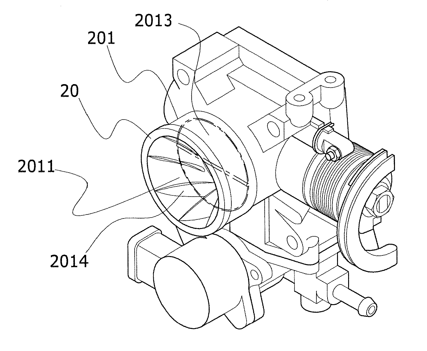
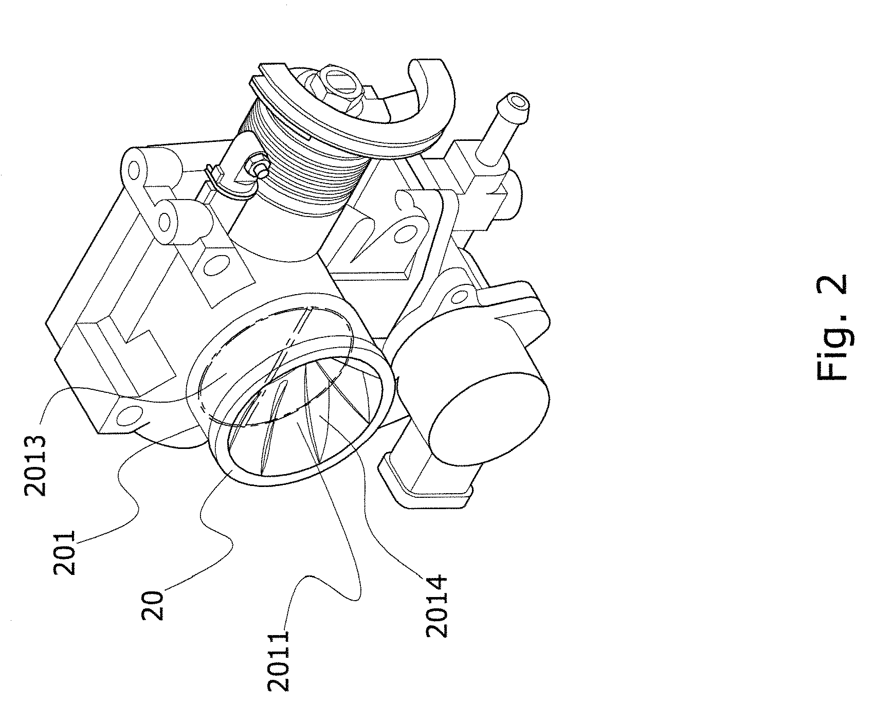
[0015]Referring to FIG. 2, which shows an external elevational view of the present invention, and an air intake device 20 depicted in the drawing is formed on an engine throttle body 201. An air inlet 2011 is formed at one end of the throttle body 201, and the air inlet 2011 is used to guide air taken in; moreover, the air inlet 2011 enables connection with an intake duct (not shown in the drawing). Another end of the throttle body 201 connects with an intake manifold (not shown in the drawing), and is used to guide the intaken air into the intake manifold. A valve 2013 is assembled interior of the throttle body 201, and pulling a throttle body cable or use of an engine computer controlled electrically operated valve (not shown in the drawing) enables an opening or closing operation of the valve 2013, thereby enabling an appropriate amount of air to be guided into the valve 2013 according to the action of the valve 2013. The inner walls of the air inlet 2011 of the air intake device...


PUM


Abstract

An air intake device, having application in engine air intake systems, and causes air to be rapidly and effectively guided into the engine fuel chambers, which primarily includes a plurality of swirl plates successively circumferentially formed on the inner walls of an air inlet end of an engine throttle body. When air is drawn into the air inlet end, then the swirl plates cause the air to form a vortex air current, which is used to increase the speed of mixing fuel with the air and improve the mixing rate, thereby enabling more complete fuel combustion in the engine fuel chambers.

Description

BACKGROUND OF THE INVENTION[0001](a) Field of the Invention[0002]The present invention relates to an air intake device, which has application in engine air intake systems, and is used to guide air into the combustion chambers of an engine for mixing with fuel to enable combustion thereof. The present invention particularly provides an air intake device able to cause intaken air to form a vortex air current.[0003](b) Description of the Prior Art[0004]Referring to FIG. 1, which shows a throttle body of an automobile engine of the prior art, wherein an air inlet 101 is formed at one end of a throttle body 10 of the drawing, and the air inlet 101 is used to guide the intake of air. The air inlet 101 is connected to an intake duct (not shown in the drawing); moreover, an air outlet 102 is formed at another end of the throttle body 10, and the air outlet 102 is connected to an intake manifold 1021, and the air outlet 102 is used to deliver the intaken air to the intake manifold 1021. A va...

Claims


Application Information

Patent Timeline
IPC IPC(8): F02B31/04F02M35/10
CPCF02B31/04F02M35/10019Y02T10/146F02M35/10281F02M35/10032Y02T10/12
Inventor CHIEN, CHANG-HO
Owner CHIEN CHANG HO
Why Eureka
Try Eureka