Method for casting metal strip with dynamic crown control

a technology of dynamic crown control and metal strip, which is applied in the direction of mould control devices, manufacturing tools,foundry moulding apparatus, etc., can solve the problems of difficult prediction of the crown shape of the casting surface between cold and casting conditions, ineffective way of dynamically controlling the roll crown

Active Publication Date: 2010-02-11
NUCOR CORP
View PDF22 Cites 8 Cited by
  • Summary
  • Abstract
  • Description
  • Claims
  • Application Information

AI Technical Summary

Benefits of technology

[0022]e. a casting roll drive system capable of counter rotating the casting rolls and varying the speed of the casting rolls during casting, and

Problems solved by technology

In casting thin strip by twin roll caster, the unpredictability of the crown in the casting surfaces of the casting rolls during a casting campaign is a difficulty.
However, the differences between the crown shape of the casting surfaces between cold and casting conditions is difficult to predict.
Yet, there has not been an effective way to dynamically control the roll crown to produce the desired profile of the cast strip until now.

Method used


Image

  • Method for casting metal strip with dynamic crown control
  • Method for casting metal strip with dynamic crown control
  • Method for casting metal strip with dynamic crown control

Examples


Embodiment Construction

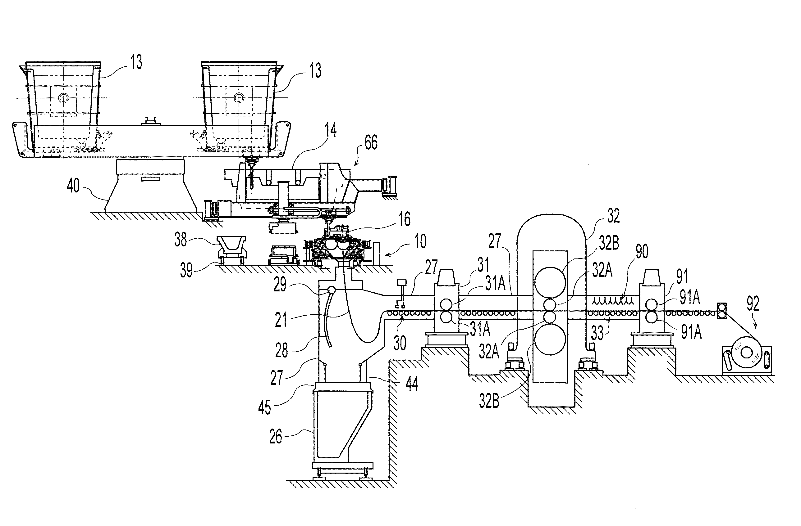
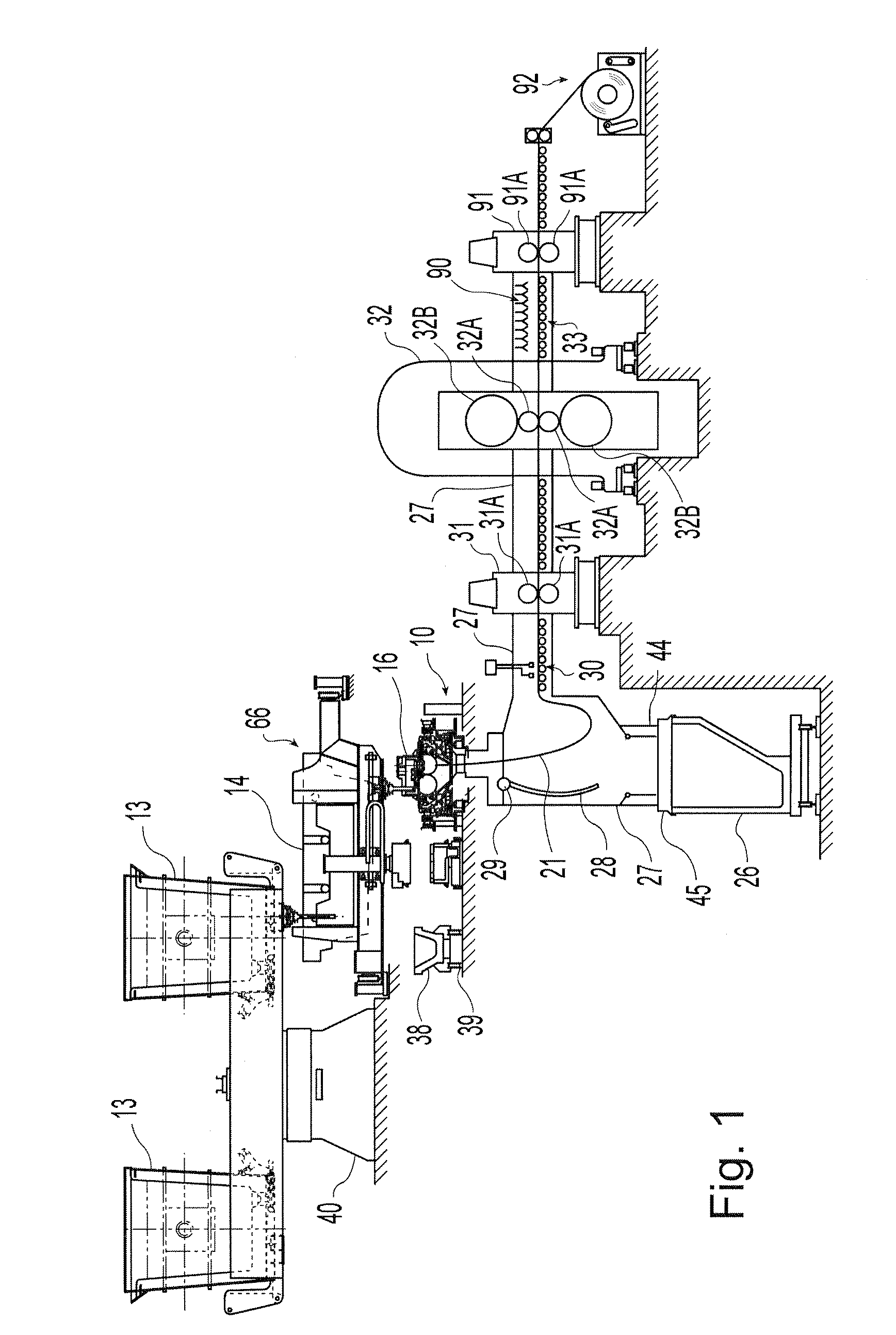
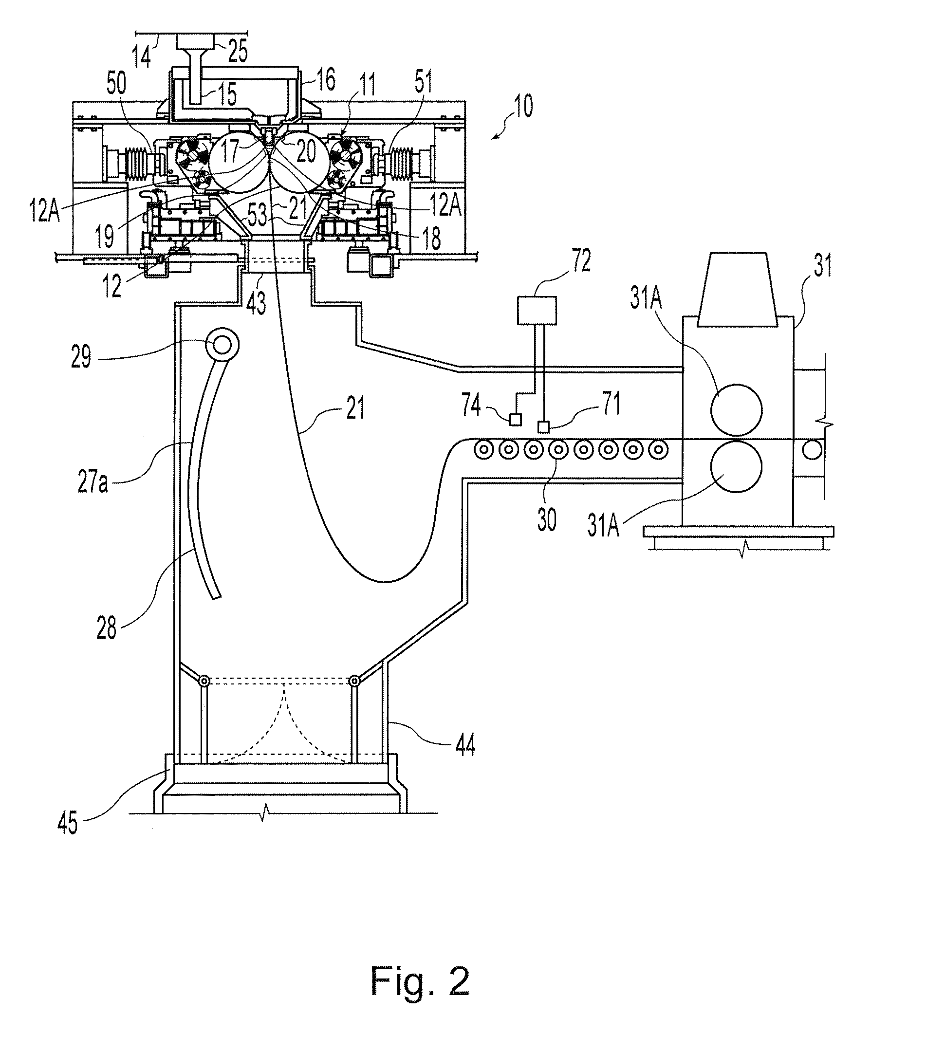
[0055]Referring now to FIGS. 1, 2, and 2A, a twin roll caster is illustrated that comprises a main machine frame 10 that stands up from the factory floor and supports a pair of counter-Rota table casting rolls 12 mounted in a module in a roll cassette 11. The casting rolls 12 are mounted in the roll cassette 11 for ease of operation and movement as described below. The roll cassette 11 facilitates rapid movement of the casting rolls 12 ready for casting from a setup position into an operative casting position in the caster as a unit, and ready removal of the casting rolls 12 from the casting position when the casting rolls 12 are to be replaced. There is no particular configuration of the roll cassette 11 that is desired, so long as it performs that function of facilitating movement and positioning of the casting rolls 12 as described herein.

[0056]The casting apparatus for continuously casting thin steel strip includes the pair of counter-Rota table casting rolls 12 having casting s...


PUM

PropertyMeasurementUnit
thicknessaaaaaaaaaa
speedaaaaaaaaaa
speedaaaaaaaaaa

Abstract

A method of continuously casting thin strip dynamically controlling roll casting surface configuration by controlling the temperature of water flowing through the longitudinal water flow passages in a cylindrical tube thickness of no more than 80 millimeters of counter rotated casting rolls, and varying the speed of the casting rolls with attenuation of the ends of the casting rolls with a casting roll drive system responsive to electrical signals received from sensors during a casting campaign.

Description

CROSS-REFERENCE TO RELATED APPLICATIONS[0001]This application is a continuation-in-part of and claims priority to and the benefit of U.S. patent application Ser. No. 12 / 186,155, filed Aug. 5, 2008,the disclosure of which is incorporated herein by reference in its entirety.BACKGROUND AND SUMMARY[0002]This invention relates to the casting of metal strip by continuous casting in a twin roll caster.[0003]In a twin roll caster, molten metal is introduced between a pair of counter-rotated horizontal casting rolls that are cooled so that metal shells solidify on the moving roll surfaces and are brought together at a nip between them to produce a solidified strip product delivered downwardly from the nip between the rolls. The term “nip” is used herein to refer to the general region at which the rolls are closest together. The molten metal may be poured from a ladle into a smaller vessel or series of smaller vessels from which it flows through a metal delivery nozzle located above the nip, ...

Claims


Application Information

Patent Timeline
Patent Type & Authority Applications(United States)
IPC IPC(8): B22D11/16B22D46/00
CPCB22D11/16B22D11/0622B22D11/06
Inventor SCHLICHTING, MARKBLEJDE, WALTER N.SCHUEREN, MIKEMAHAPATRA, RAMA BALLAV
Owner NUCOR CORP
Why Eureka
Try Eureka