
Image capture method and system using a virtual sensor

a virtual sensor and image capture technology, applied in the field of image capture systems, can solve the problems of tracking system inadvertent obstruction of sportspersons or sports equipment, safety problems, and certain degree of dexterity required, and achieve the effect of reducing the risk of collision and preventing the collision

Active Publication Date: 2019-10-31
COURTES ALEXANDRE
View PDF21 Cites 2 Cited by
  • Summary
  • Abstract
  • Description
  • Claims
  • Application Information

AI Technical Summary

Benefits of technology

This patent describes a method for capturing multiple images of the same scene from different angles and viewpoints simultaneously, which offers an operator a wider range of shots. The method also allows for different relative speeds of the subject and virtual sensor in the reconstructed video sequence. It provides flexibility in reconstiving the video sequence while avoiding safety and accidents. The system uses a linearization function and a tracking algorithm to fix the relative distance or speed between the virtual sensor and the sportsperson. This technology is advantageous for conducting research and analysis of sports events.

Problems solved by technology

However, in view of the speed of movement involved, for example of the order of several hundred km / hour for a vehicle, a certain degree of dexterity is required for operating the tracking system, and it only offers a small margin for manoeuvre with respect to image capture (the viewing angle is predetermined) and focus.
Moreover, the movement of tracking systems near the sportsperson may lead to safety problems.
In fact, the tracking system may inadvertently obstruct and crash into the sportsperson or sports equipment through an operating error or a mechanical problem with the tracking system.
Furthermore, the movement of one or more tracking systems on the course (or circuit) may obstruct the sportsperson's clear view of the course and thus increase the risk of an accident.

Method used


Image

  • Image capture method and system using a virtual sensor
  • Image capture method and system using a virtual sensor
  • Image capture method and system using a virtual sensor

Examples


Embodiment Construction

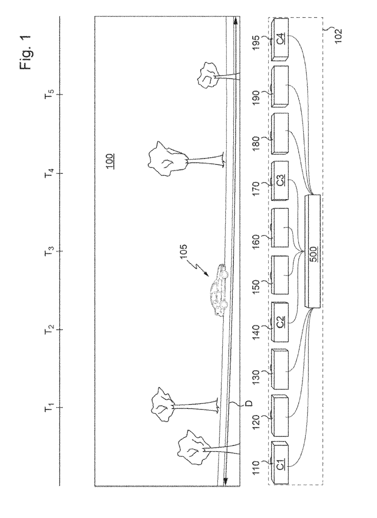
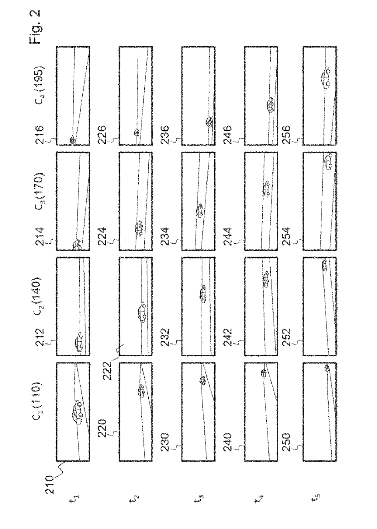
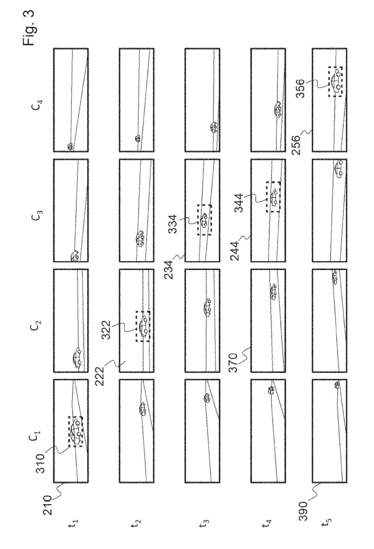
[0051]In general, the present invention makes it possible to carry out virtual tracking, allowing a user of the image capture system (typically a camera operator) to navigate virtually in a video channel, i.e. change the viewpoint in real time and for example carry out virtual modification of the speed or direction of movement of a virtual sensor.

[0052]With the present invention, it is possible to obtain images similar to those obtained by tracking the subject (e.g. a sportsperson or sports equipment), for example parallel to their movement, with the additional advantage of being able to alter the relative speed of the virtual sensor relative to the moving object.

[0053]Thus, a larger number of different viewpoints may be envisaged during one and the same video capture than in the prior art.

[0054]FIG. 1 is a diagrammatic representation of a context in which embodiments of the invention may be implemented.

[0055]In particular, it is a context in which an image capture system according ...


PUM


Abstract

Disclosed is an image capture method using a virtual tracking sensor, implemented in an image capture system including wide-field image acquisition devices, each placed at a different fixed position along the course, such that the images captured at a given instant in time by two different acquisition devices represent different points of view of athletes traveling over the course. The method includes: capturing, in real time, images representative of an area in space that is substantially equivalent to the predetermined course, by each acquisition device of the plurality; selecting, for each instant in time of a plurality of successive instants in time, a given acquisition device and a portion of the image captured thereby at the instant in time; and reconstructing, on the basis of the selected image portions, a video sequence similar to that which would have been captured by an acquisition device moving along the course.

Description

FIELD OF THE INVENTION[0001]The present invention relates to image capture systems, which may for example equip circuits or courses for high-speed sports.[0002]It relates in particular to an image capture method using a virtual sensor for tracking a sportsperson or sports equipment moving at high speed over a predetermined course, said method making it possible to produce a video sequence, as well as an image capture system.CONTEXT OF THE INVENTION[0003]Image capture takes place in numerous applications, making it necessary to satisfy increasingly specific constraints.[0004]One example of application is video capture of an object (or subject) moving at very high speed, typically in a high-speed sports context, for example a sportsperson (for example a skier) or sports equipment such as a ball or a racing motor vehicle. Such a vehicle may travel at speeds of the order of 300 km / hour.[0005]Video capture of such a subject, for example for television or cinema, is generally carried out ...

Claims


Application Information

Patent Timeline
Patent Type & Authority Applications(United States)
IPC IPC(8): H04N13/282H04N5/217H04N5/268H04N5/247H04N23/90
CPCH04N5/247H04N5/268H04N13/282H04N5/217H04N5/262H04N23/90H04N23/81
Inventor COURTÈS, ALEXANDRE
Owner COURTES ALEXANDRE
Learn More