
Touch screen and method for positioning coordinate

a technology of coordinate positioning and touch screen, which is applied in the field of touch control technology, can solve the problems of low resolution of resistive sensors, inability to precisely position coordinates, and damage to liquid crystal displays, so as to reduce manufacturing costs of printed circuit boards or indium tin oxide glasses, and improve sensing resolution

Inactive Publication Date: 2010-02-11
ELAN MICROELECTRONICS CORPORATION
View PDF9 Cites 12 Cited by
  • Summary
  • Abstract
  • Description
  • Claims
  • Application Information

AI Technical Summary

Benefits of technology

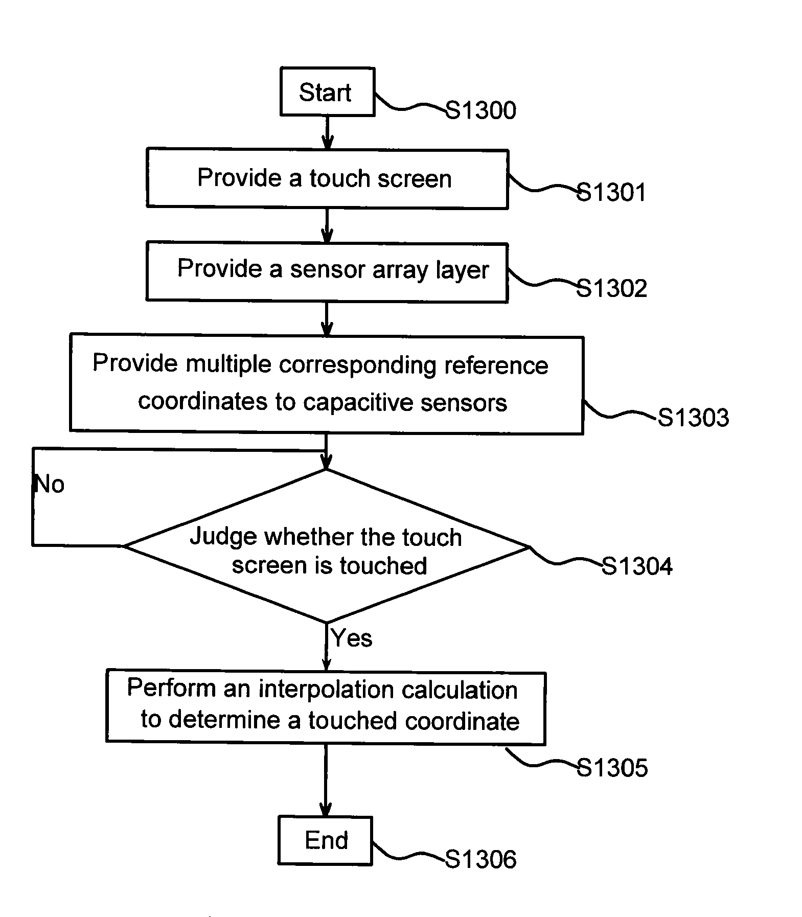
[0009]In view of this, it is therefore an objective of the present invention to provide a coordinate positioning method and a touch screen using the same, wherein two-dimensional plane coordinates are obtained by way of one-dimensional sensing. Thus, the sensing resolution is increased, and the manufacturing cost of a printed circuit board or an indium tin oxide (ITO) glass is lowered.
[0014]The spirit of the present invention is to provide a sensor array layer in a touch panel, wherein the sensor array layer has M×N capacitive sensors, M rows of the capacitive sensors are disposed along the first axis, N columns of the capacitive sensors are disposed along the second axis, and each capacitive sensor is coupled to a microprocessor. Thus, when the touch panel is touched, the sensing value of the capacitive sensor located at the corresponding position is changed, and the touched position may be obtained by way of calculation. Because the structure is obviously different from the conventional touch panel, the present invention only needs one sensing layer to perform the coordinate positioning, which has to be achieved in the prior art using two sensing layers. Thus, the sensing resolution is increased, and the manufacturing cost of the printed circuit board or the indium tin oxide (ITO) glass may be further reduced as compared with the prior art.

Problems solved by technology

After a long period of time, the liquid crystal display may be thus damaged.
In addition, the resistive sensor has the lower resolution, and the coordinate often cannot be positioned precisely.
Thus, the manufacturing procedure is complicated, and the cost requirement also becomes higher.

Method used


Image

  • Touch screen and method for positioning coordinate
  • Touch screen and method for positioning coordinate
  • Touch screen and method for positioning coordinate

Examples


Embodiment Construction

[0032]The present invention will be apparent from the following detailed description, which proceeds with reference to the accompanying drawings, wherein the same references relate to the same elements.

[0033]FIG. 5 shows the circuit structure of a touch screen according to an embodiment of the present invention. Referring to FIG. 5, the capacitive touch screen includes a sensor array layer 501 and a microprocessor 502. In this embodiment, the sensor array layer 501 includes 12 capacitive sensors 50 arranged in a 3×4 array. Each capacitive sensor 50 is coupled to the microprocessor 502. The capacitive sensors 50 respectively have representative coordinates (0, 0) to (4, 3).

[0034]When the finger of the human body or any conductive material does not contact with the capacitive touch screen, the capacitance of the capacitive sensor 50 is kept unchanged. Therefore, each capacitor sensing value received by the microprocessor 502 does not fluctuate. Generally speaking, the microprocessor 5...


PUM


Abstract

The present invention relates to a touch screen and a method for positioning a coordinate. The touch screen includes a sensor array layer and a microprocessor. The sensor array layer includes M×N capacitive sensors, wherein M rows of the capacitive sensors are disposed along a first axis, and N columns of the capacitive sensors are disposed along a second axis. The microprocessor includes a plurality of pins correspondingly coupled to the capacitive sensors. When the touch screen is touched to change at least one of sensing values of the capacitive sensors in the sensor array layer, the microprocessor performs an interpolation calculation to determine a touched coordinate according to the sensing values sensed by the capacitive sensors.

Description

[0001]This application claims priority of No. 097129599 filed in Taiwan R.O.C. on Aug. 5, 2008 under 35 USC 119, the entire content of which is hereby incorporated by reference.BACKGROUND OF THE INVENTION[0002]1. Field of the Invention[0003]The present invention relates to the touch-control technology, and more particularly to a touch screen and a coordinate positioning method.[0004]2. Related Art[0005]Recently, due to the rapid development of the technology, handheld devices, such as a smart mobile phone, a digital personal assistant (PDA), a global position system (GPS) and the like, have become more and more popular. Because touch screens are used in the above-mentioned devices, the technology of the touch sensor becomes very important. In the prior art, the typically used touch sensor is a resistive sensor. This resistive sensor has to sense the coordinate on the screen according to the pressure. A liquid crystal display is usually used in the handheld device, and the resistive ...

Claims


Application Information

Patent Timeline
Patent Type & Authority Applications(United States)
IPC IPC(8): G06F3/045
CPCG06F3/044G06F3/0416G06F3/041661G06F3/0443G06F3/0446
Inventor CHIU, YEN-CHENHSI, MING CHIEH
Owner ELAN MICROELECTRONICS CORPORATION
Learn More