Shooting lens having vibration reducing function and camera system for same
a technology of vibration reduction and shooting lens, which is applied in the field of shooting lens, can solve the problems of vibration decreasing, vibration decreasing, and the value of the dc offset and drift measured for shipment is not usable for actual shooting, and achieves the effects of accurate correction, correcting properly and stably, and high robustness of the reference signal against external disturban
- Summary
- Abstract
- Description
- Claims
- Application Information
AI Technical Summary
Benefits of technology
Problems solved by technology
Method used
Image
Examples
first embodiment
Description of Structure of First Embodiment
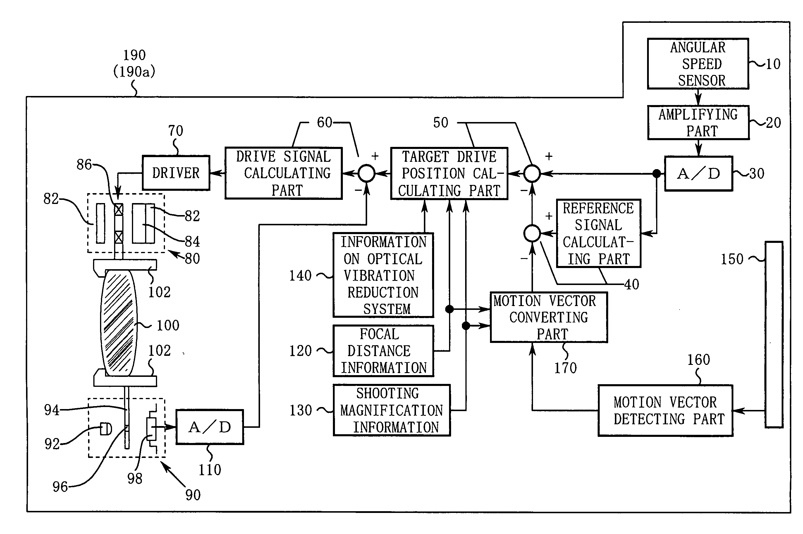
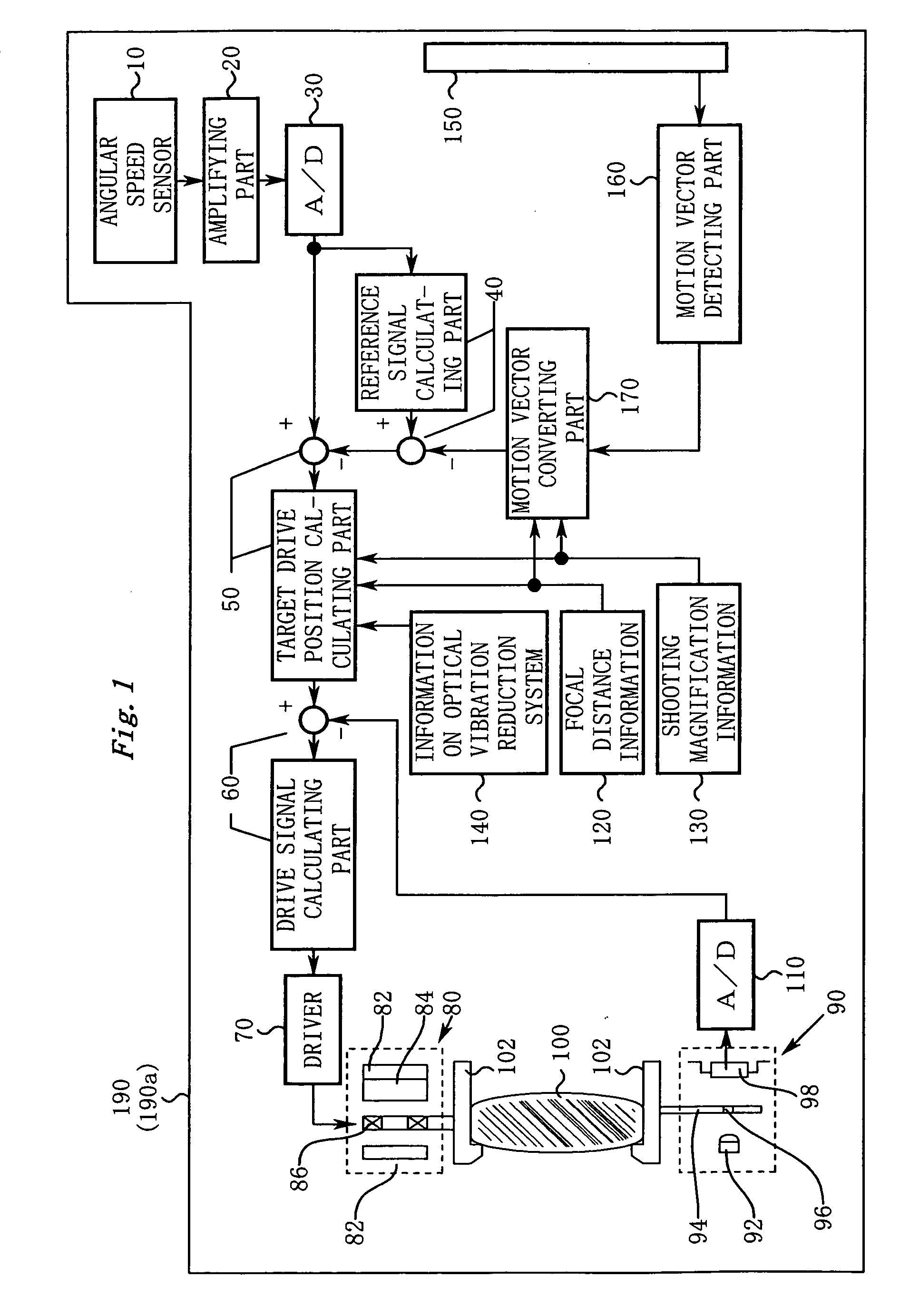
[0076]FIG. 1 shows a schematic block diagram of a camera system 190 (including a shooting lens 190a) according to the first embodiment of the present invention. In reality, the camera system 190 reduces a vibration of an image in two axis directions, horizontal and vertical directions. However, for simplicity, in FIG. 1, a vibration reduction mechanism for one axis is shown.
[0077]Next, the structure of each part shown in FIG. 1 will be described.
[0078]An angular speed sensor 10 detects a vibration of the camera system 190 as an angular speed using Coriolis force. An amplifying part 20 amplifies an output of the angular speed sensor 10. In addition, a low-pass filter may be disposed to reduce a high frequency noise in the sensor output. An A / D converting part 30 converts an output of the amplifying part 20 into digital angular speed data.
[0079]A reference signal calculating part 40 extracts a low frequency component from the angular speed d...
second embodiment
Description of Structure of Second Embodiment
[0119]FIG. 8 is a schematic diagram showing a camera system 290 (including a shooting lens 290a) according to a second embodiment of the present invention. FIG. 9 is a block diagram showing a principal structure of a vibration reduction control system.
[0120]Next, with reference to FIG. 8 and FIG. 9, the structure of each part of the camera system 290 will be described. For simplicity, description of structural parts that are in common with the first embodiment (FIG. 1) will be omitted.
[0121]First of all, a target drive position calculating part 50 (in detail, a part denoted by reference numeral 50a in FIG. 8) subtracts a reference signal from angular speed data so as to obtain an actual angular speed as a cause of a vibration of an image.
[0122]The target drive position calculating part 50 (in detail, a part denoted by reference numeral 50b in FIG. 8) converts the actual angular speed into a scale of the moving amount of a optical vibratio...
third embodiment
Description of Structure of Third Embodiment
[0169]FIG. 13 is a schematic diagram showing a camera system (including a shooting lens 390a).
[0170]Next, with reference to FIG. 13, the structure of each part of the camera system 390 will be described. For simplicity, description of structural parts that are in common with the first embodiment (FIG. 1) will be omitted.
[0171]The third embodiment features a structure of which a gain changing part 200′ is disposed. The gain changing part 200′ adjusts the gain of a motion vector.
[0172]Connected to the gain changing part 200′ is a release button 201, a focus detecting part 202 that determines whether or not a subject is focused, and a panning detecting part 203 that determines whether or not the camera is panning.
[Relation Between the Claims and the Third Embodiment]
[0173]Next, the relation between the terminology used in claims and the terminology used in the third embodiment will be described. It should be noted that the relation represents...
PUM
 Abstract
Description
Claims
Application Information
 - R&D
- Intellectual Property
- Life Sciences
- Materials
- Tech Scout
- Unparalleled Data Quality
- Higher Quality Content
- 60% Fewer Hallucinations
Browse by: Latest US Patents, China's latest patents, Technical Efficacy Thesaurus, Application Domain, Technology Topic, Popular Technical Reports.
© 2025 PatSnap. All rights reserved.Legal|Privacy policy|Modern Slavery Act Transparency Statement|Sitemap|About US| Contact US: help@patsnap.com


