Multilayer chip capacitor

Active Publication Date: 2010-02-11
SAMSUNG ELECTRO MECHANICS CO LTD
View PDF4 Cites 11 Cited by
  • Summary
  • Abstract
  • Description
  • Claims
  • Application Information

AI Technical Summary

Benefits of technology

[0012]An aspect of the present invention provides a multilayer chip capacitor capable of reducing a PDN impedance to a tar

Problems solved by technology

A power distribution network (PDN) of a micro processor unit (MPU) is designed

Method used


Image

  • Multilayer chip capacitor
  • Multilayer chip capacitor
  • Multilayer chip capacitor

Examples


Example

[0063]Exemplary embodiments of the present invention will now be described in detail with reference to the accompanying drawings. This invention may, however, be embodied in many different forms and should not be construed as limited to the embodiments set forth herein. Rather, these embodiments are provided so that this disclosure will be thorough and complete, and will fully convey the scope of the invention to those skilled in the art. In the drawings, the shapes and dimensions may be exaggerated for clarity, and the same reference signs are used to designate the same or similar components throughout.

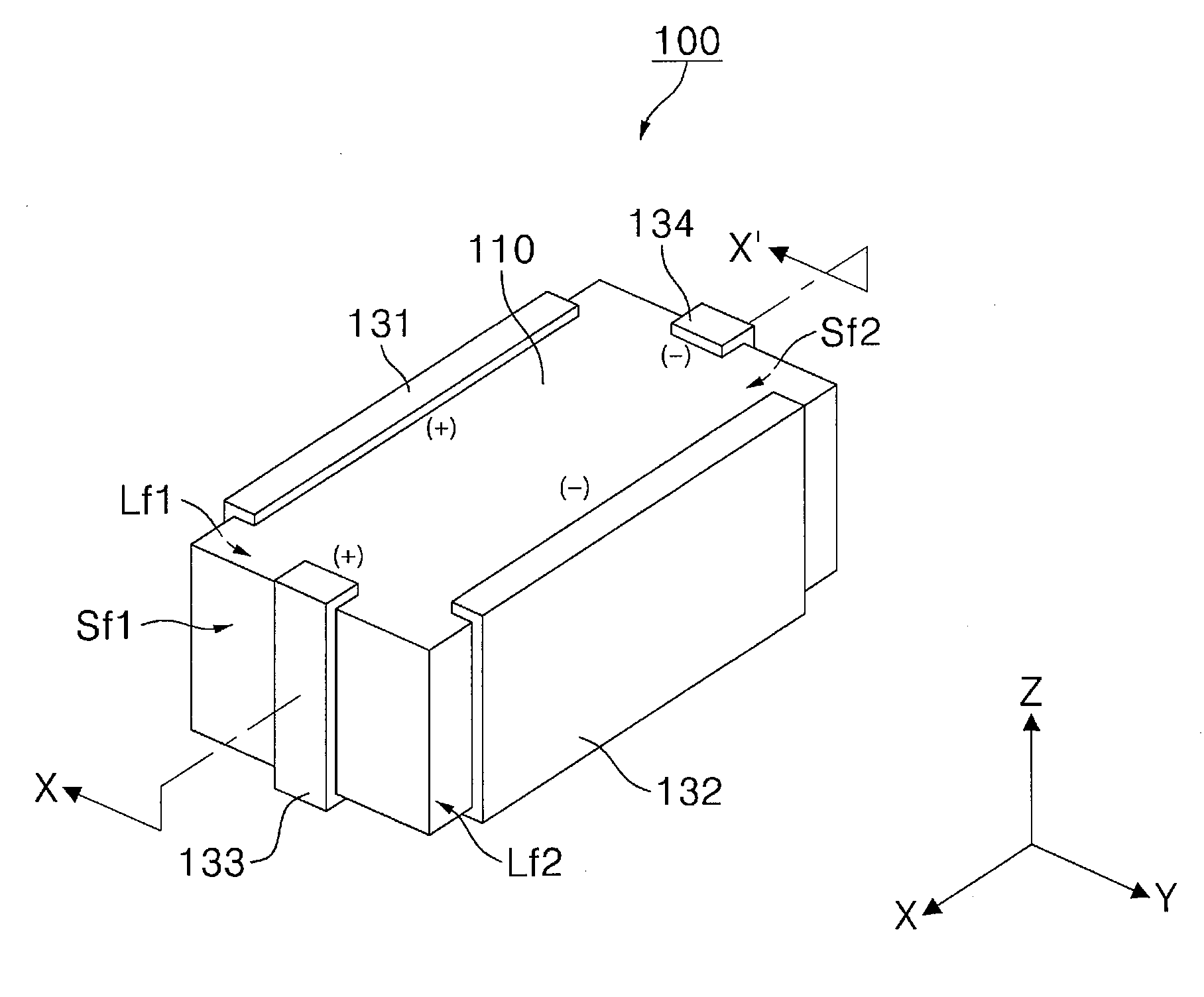
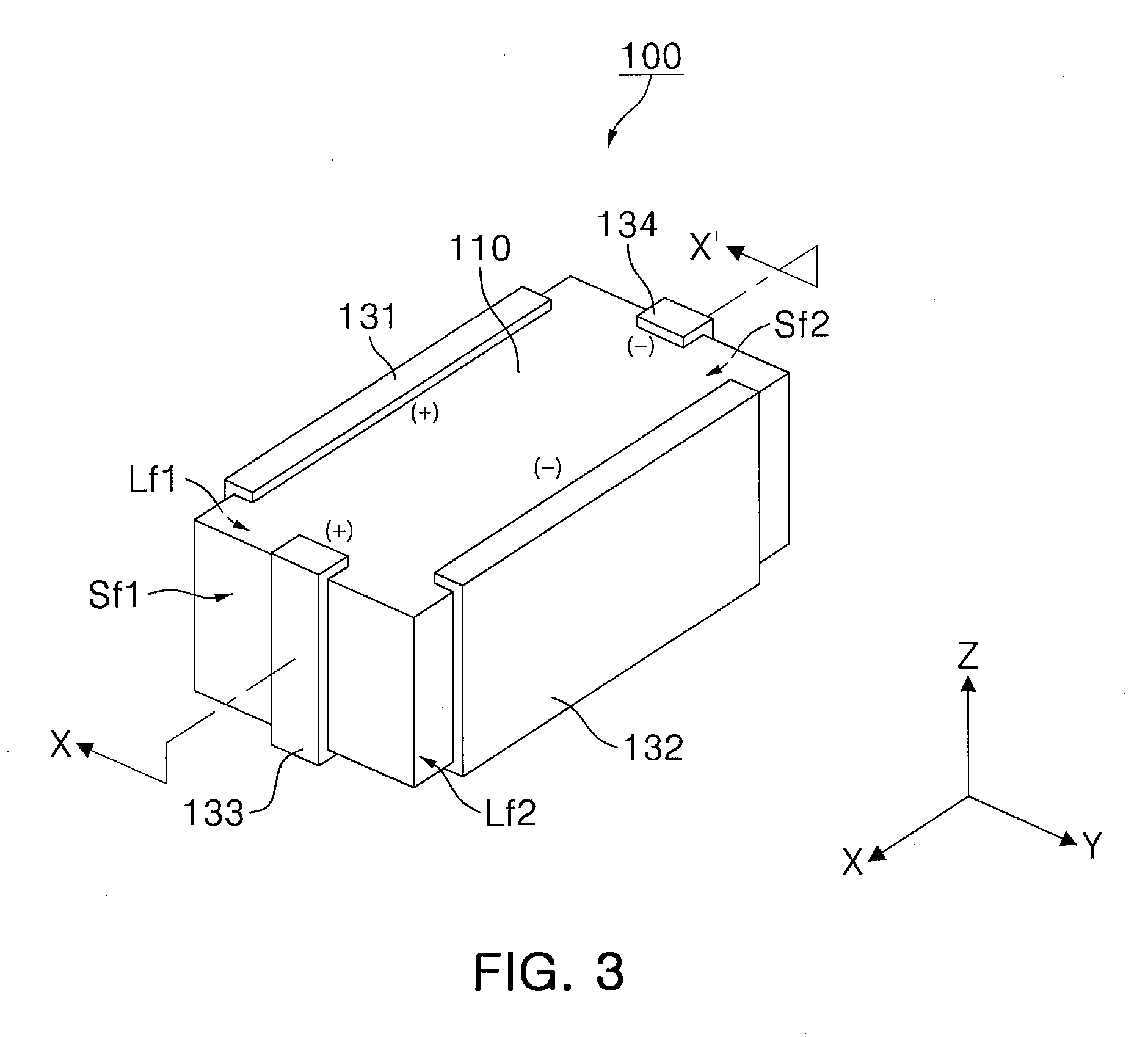
[0064]FIG. 3 is a perspective view illustrating an appearance of a multilayer chip capacitor according to an exemplary embodiment of the invention. FIG. 4 is a cross-sectional view of the multilayer chip capacitor of FIG. 3, taken along the line X-X′. FIG. 5 is a plan view illustrating an inner electrode structure of the capacitor shown in FIG. 3

[0065]Referring to FIGS. 3 to 5, the c...


PUM


Abstract

There is provided a multilayer chip capacitor a multilayer chip capacitor including: a capacitor body including first and second capacitor units arranged therein; and first to fourth outer electrodes, wherein the first capacitor unit includes first and second inner electrodes, and the first capacitor unit includes a plurality of capacitor elements each having a pair of the first and second inner electrodes repeatedly laminated, the second capacitor unit includes third and fourth inner electrodes, and the second capacitor unit includes at least one capacitor element having a pair of the third and fourth inner electrodes repeatedly laminated, and at least one of the capacitor elements of the first capacitor unit is different from the other capacitor elements of the first capacitor unit in a lamination number of the first and second inner electrodes or a resonant frequency.

Description

CROSS-REFERENCE TO RELATED APPLICATIONS[0001]This application claims the priority of Korean Patent Application No. 2008-0077971 filed on Aug. 8, 2008, in the Korean Intellectual Property Office, the disclosure of which is incorporated herein by reference.BACKGROUND OF THE INVENTION[0002]1. Field of the Invention[0003]The present invention relates to a multilayer chip capacitor, and more particularly, to a multilayer chip capacitor suitably used as a decoupling capacitor of a power distribution network of a microprocessor unit (MPU) and capable of reducing a power distribution network impedance to a target impedance or less in a broad frequency range as a single capacitor.[0004]2. Description of the Related Art[0005]A power distribution network (PDN) of a micro processor unit (MPU) is designed with increasing difficulty due to higher speed and more integration of the MPU. Notably, a decrease in a power voltage and an increase in an MPU consumption current resulting from more integrat...

Claims


Application Information

Patent Timeline
IPC IPC(8): H01G4/38
CPCH01G4/012H01G4/232H01G4/38H01G4/35H01G4/30H01G4/33
Inventor LEE, BYOUNG HWAWI, SUNG KWONCHUNG, HAE SUKPARK, DONG SEOKPARK, SANG SOOPARK, MIN CHEOL
Owner SAMSUNG ELECTRO MECHANICS CO LTD
Why Eureka
Try Eureka