Compression brace

a compression brace and bracing technology, applied in the field of orthopaedic surgery, can solve the problems of inconvenient operation, high manufacturing cost, and difficulty in positioning the bones such that they align with the legs of the staple, so as to increase intra-operative choices and reduce inventory

a compression brace and bracing technology, applied in the field of orthopaedic surgery, can solve the problems of inconvenient operation, high manufacturing cost, and difficulty in positioning the bones such that they align with the legs of the staple, so as to increase intra-operative choices and reduce inventory

US20100036430A1Inactive Publication Date: 2010-02-11WRIGHT MEDICAL TECH

Image

  • Compression brace
  • Compression brace
  • Compression brace

Examples


Embodiment Construction

[0040]In the following detailed description of the preferred embodiments, reference is made to the accompanying drawings which form a part hereof, and in which are shown by way of illustration specific embodiments in which the invention may be practiced. It is to be understood that other embodiments may be utilized and structural changes may be made without departing from the scope of the present invention.

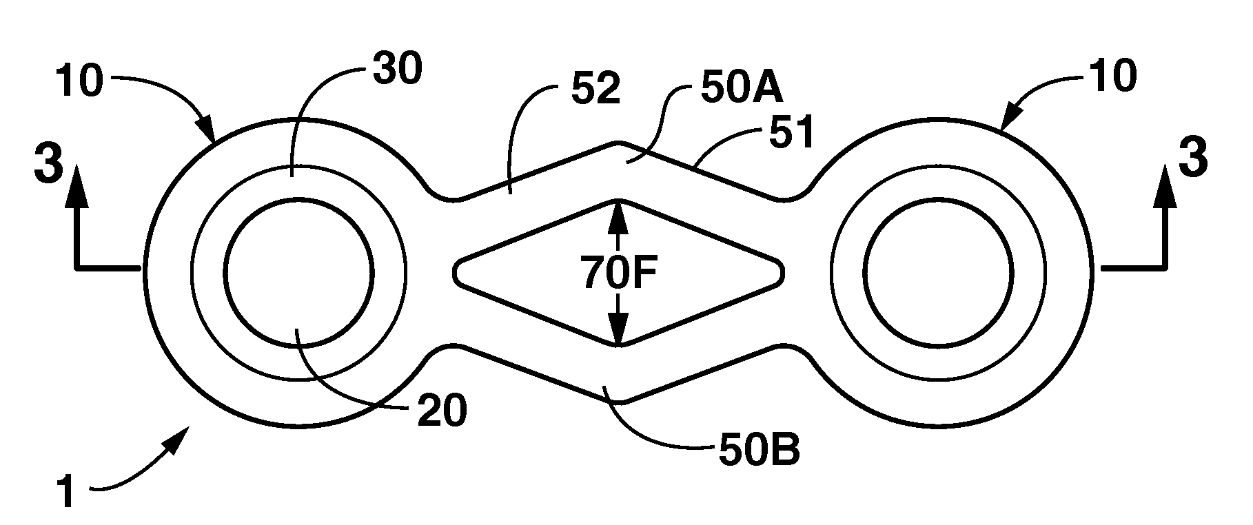
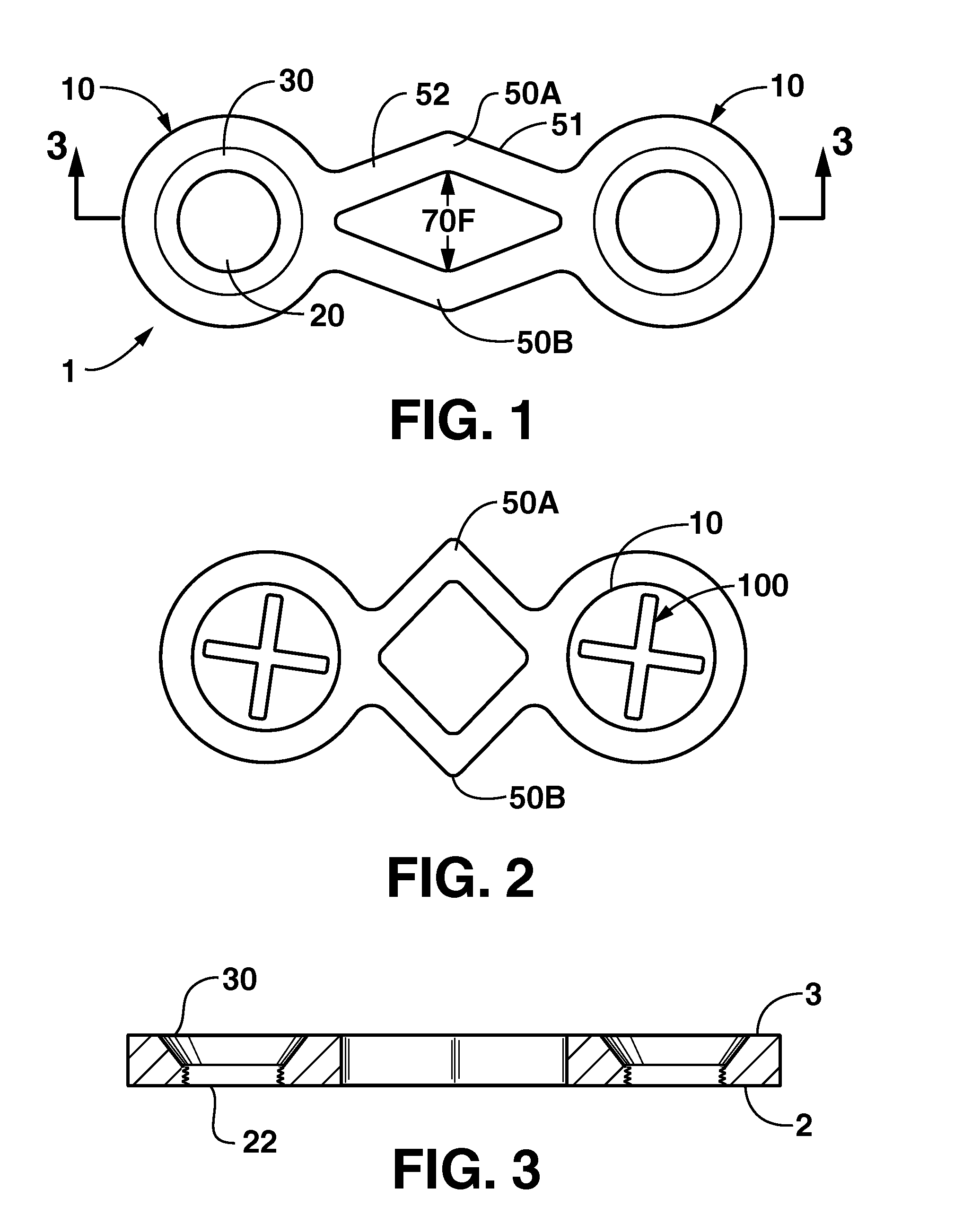
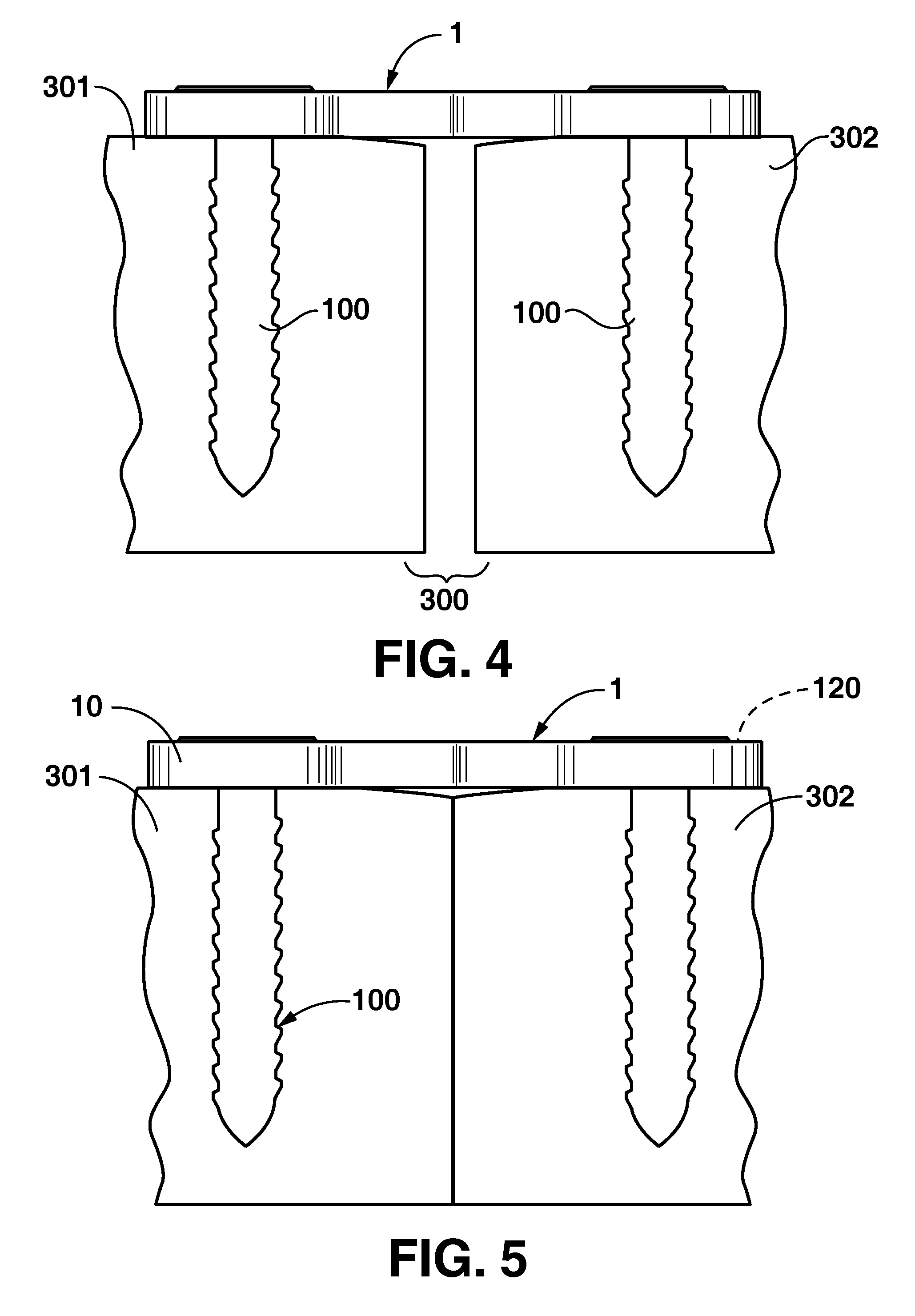
[0041]As shown in FIGS. 4 and 5, the invention is a surgical device for pressing and retaining adjacent bones 301, 302 against one another, such as to reduce a fracture. As shown in the uncompressed configuration of FIG. 4, the invention includes, generally, a compression brace 1 and fasteners 100 for securing the brace on bones 301, 302. As indicated in the compressed configuration of FIG. 5, compression of the brace 1 presses the adjacent bone fragments 301, 302 together.

[0042]As shown in FIG. 1, in a preferred embodiment the compression brace 1 has at least two fastener retaini...


PUM


Abstract

A surgical device for pressing and retaining adjacent bones against one another comprising a compression brace and separate fasteners. The compression brace has at least two fastener retaining portions. Each fastener retaining portion has a fastener hole therethrough for receiving a fastener, such as a screw or pin. A pair of bridge members are positioned between the fastener retaining portions, and are spaced apart from one another to form a compression opening. The compression bracket can include a plurality of fastener retaining portions and a plurality of compression openings. In some embodiments, the fasteners are maintained in a substantially fixed relation with the fastener retaining portion. The brace is installed on adjacent bones such that a fastener engages each bone. The compression opening is spread apart to draw the fasteners toward one another, and thereby compress the adjacent bones together.

Description

CROSS REFERENCE TO RELATED APPLICATIONS[0001]This application is a continuation of U.S. patent application Ser. No. 10 / 940,396, which was filed on Sep. 14, 2004, the entirety of which is herein incorporated by reference.STATEMENT REGARDING FEDERALLY SPONSORED RESEARCH OR DEVELOPMENT[0002]Not applicable.REFERENCE TO A MICROFICHE APPENDIX[0003]Not applicable.FIELD OF THE INVENTION[0004]The present invention relates generally to orthopedic surgery, and more particularly to devices and methods for reduction of fractures and osteotomies by drawing bones together.BACKGROUND OF THE INVENTION[0005]U.S. Pat. No. 2,597,342 (Lang) discloses the use of a compressible fastener for joining boards together. The Lang fastener includes a central loop portion and claw members that extend from diametrically opposed sides of the central loop. The loop is preferably a parallelogram. Each claw member has two claws. Each claw has downwardly turned ends with inwardly turned portions which are configured to...

Claims


Application Information

Patent Timeline
11 Feb 2010
Publication
US20100036430A1
IPC
A61B17/88; A61B17/66; A61B17/80
CPC
A61B17/1728; A61B17/7059; A61B17/8085; A61B17/86; A61B17/8605; A61B17/8872; A61B2017/681; A61B2019/307
Inventors
HARTDEGEN, VERNON R.; WONG, KEVIN