Flow Compensated Proportional Bypass Valve Combined With a Control Valve

a proportional bypass valve and control valve technology, applied in the direction of process and machine control, positive displacement liquid engine, instruments, etc., can solve the problems of slight metered flow accuracy error, different pressure differential (p) across the bypass valve, etc., and achieve the effect of reducing or eliminating the p difference and little or no error

Active Publication Date: 2010-02-18
WOODWARD GOVERNOR CO
View PDF14 Cites 19 Cited by
  • Summary
  • Abstract
  • Description
  • Claims
  • Application Information

AI Technical Summary

Benefits of technology

[0005]The present invention corrects for such inaccuracy by adding a compensating area and an orifice drop at the bypass inlet with a proportional and control valve to both bypass pump flow and regulate pumped flow in the form of an integrated common regulator valve. This reduces or eliminates the ΔP difference at the metering valve resulting in little or no error.

Problems solved by technology

It has been recognized by the present inventors that the disadvantage of variable displacement pumping schemes such as in the '674 and '485 patents is that at high system pressures, the pressure differential (ΔP) across the bypass valve is different than at low system pressures.
This slight ΔP difference across the main metering valve results in a slight metered flow accuracy error.

Method used


Image

  • Flow Compensated Proportional Bypass Valve Combined With a Control Valve
  • Flow Compensated Proportional Bypass Valve Combined With a Control Valve
  • Flow Compensated Proportional Bypass Valve Combined With a Control Valve

Examples


Embodiment Construction

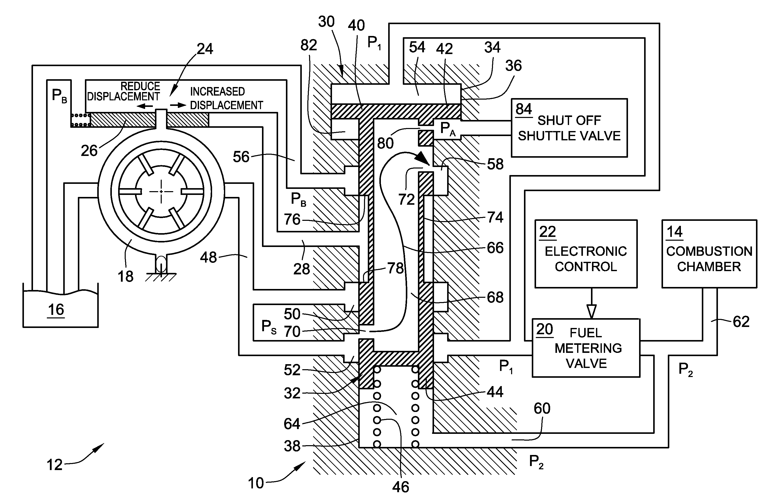
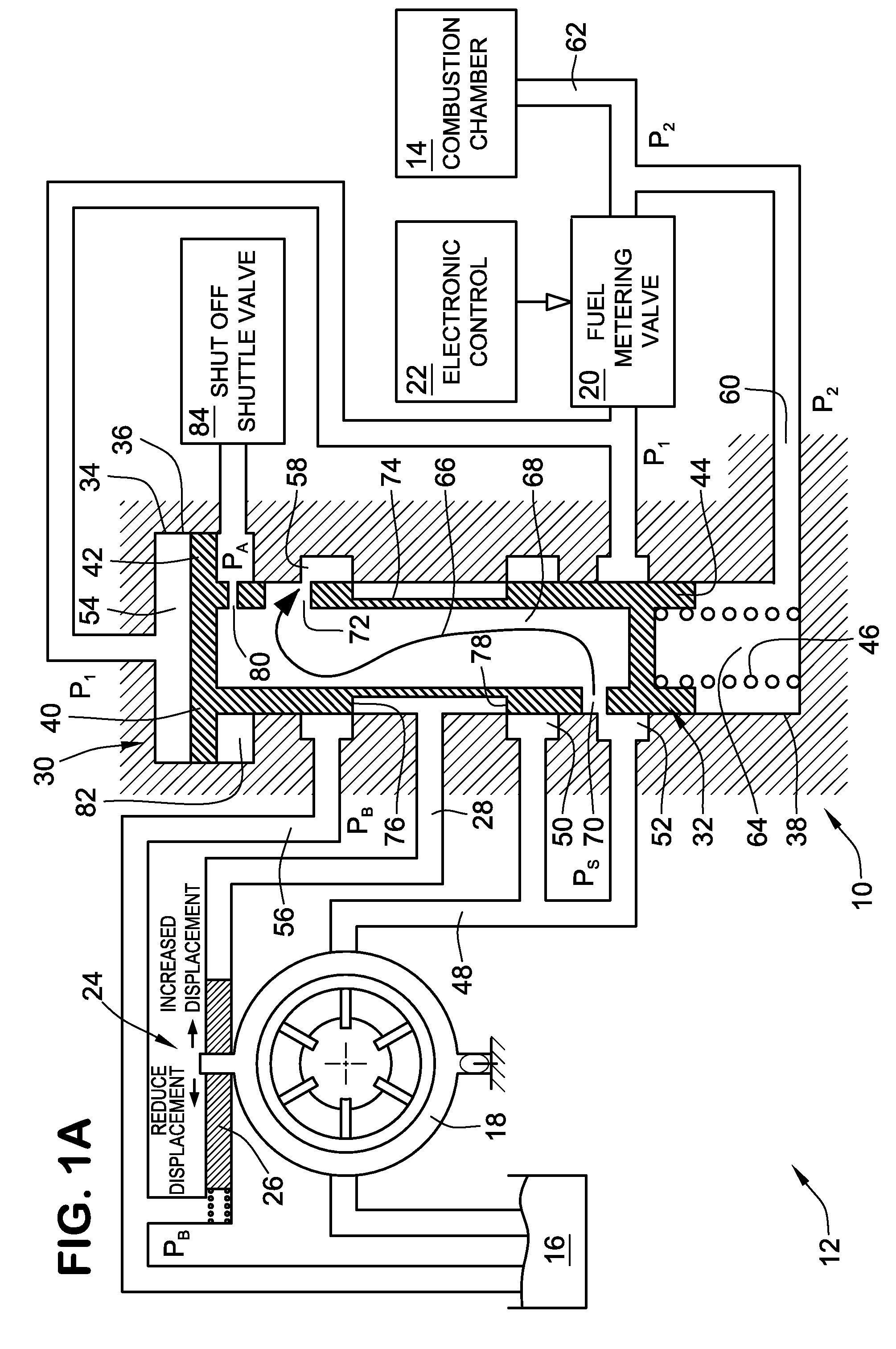
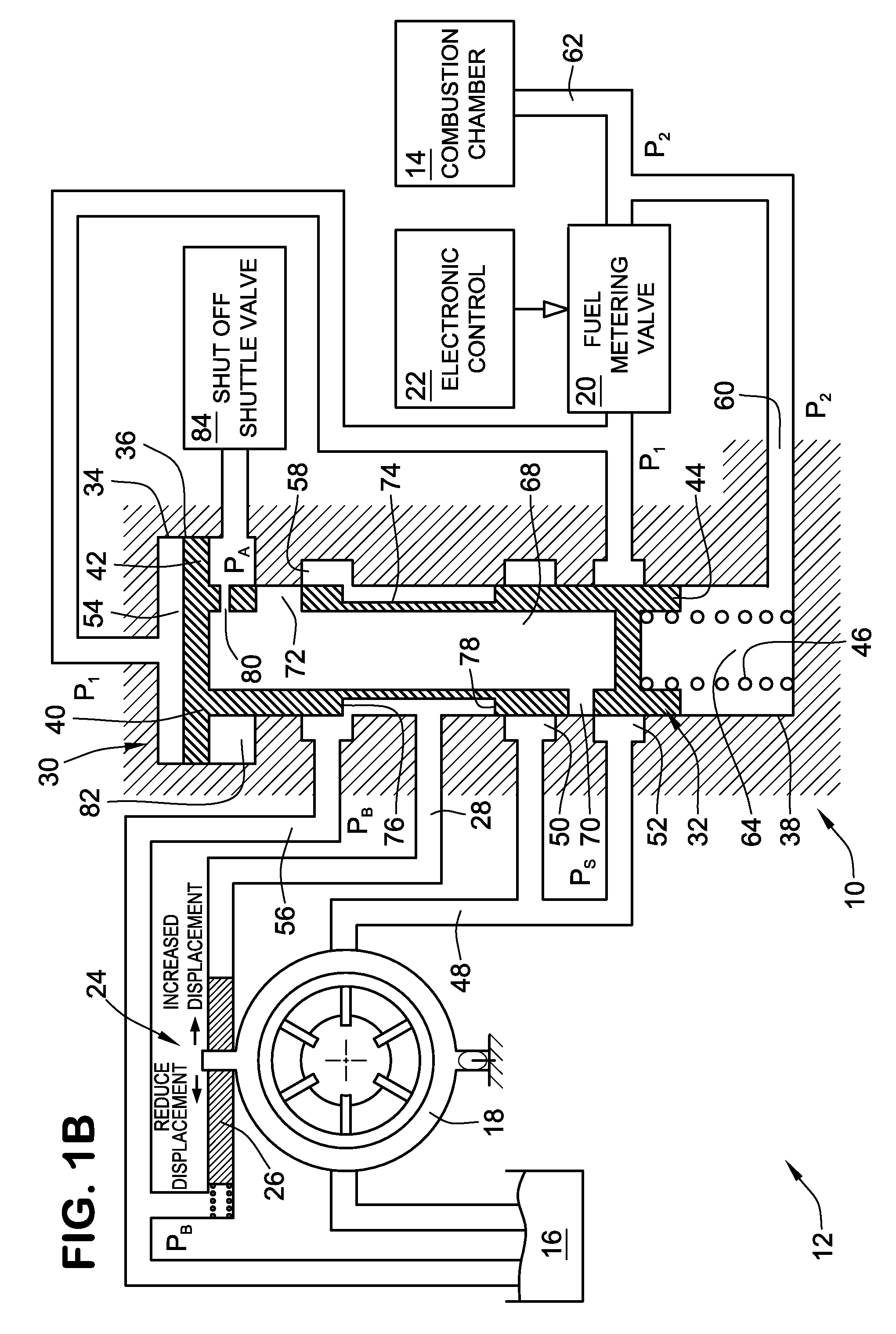
[0018]For purposes of illustration, a regulator valve 10, according to a first embodiment of the present invention, is shown in FIGS. 1A-1C. The regulator valve 10 may be incorporated into a variable displacement pumping system 12 for delivering pressurized liquid fuel to nozzles of a combustion chamber 14. For example, this system 12 may be employed in a gas turbine engine that is adapted to drive a rotary compressor. Fuel for the engine is contained at a sump pressure Pb in a fuel tank 16 and upstream fluid lines of the pump. A variable displacement pump 18 is adapted to pressurize and deliver fuel from the fuel tank 16 through various valves to the combustion chamber 14. Between the variable displacement pump 18 and the combustion chamber 14 is a servo-controlled fuel metering valve 20, which may be positioned by appropriate position feedback and an electronic control 22.

[0019]The regulator valve 10 is arranged and configured to perform two functions, including: (a) bypassing a c...


PUM


Abstract

A common regulator valve is provided for a variable displacement pump fuel metering scheme in which the common regulator valve both controls working output to a pump actuator to control displacement of the variable displacement pump and also to control bypass of excess fuel flow. The regulator valve also includes a differential piston which generates a compensation force off of the bypass flow in order to compensate for changes in spring force and flow reaction force at different system pressures and operational states. As a result, errors in the metered fuel flow can be either eliminated or substantially reduced.

Description

FIELD OF THE INVENTION[0001]The invention generally relates to regulator valves and more particularly relates to regulator valves and regulator schemes for controlling variable displacement pumps and for bypassing flow, such as in fuel deliver systems for gas turbine engines.BACKGROUND OF THE INVENTION[0002]In fuel delivery systems for gas turbine engines, it is well known to bypass a certain portion of the pumped flow by using the pressure differential generated across a fuel metering valve. Examples of bypass valves with differential pistons to provide compensating area to adjust for different system pressures are shown, for example, in Wernberg, U.S. Pat. No. 4,458,713 and Kao et al., U.S. Pat. No. 5,433,237, the full disclosures of which are hereby incorporated by reference.[0003]Additionally, the state of the art also includes more recent attempts at providing a variable displacement pump fuel metering scheme which use a proportional and integral control valve to bypass pump fl...

Claims


Application Information

Patent Timeline
Patent Type & Authority Applications(United States)
IPC IPC(8): G05D11/00
CPCG05D7/0688F02C9/30F02C7/232F02C7/22Y10T137/2605
Inventor TYSVER, JOHN D.BAKER, CARTHEL C.KLECKLER, JOEL W.
Owner WOODWARD GOVERNOR CO
Why Eureka
Try Eureka