Suck-back valve

a technology of suck-back valve and actuator, which is applied in the direction of valve operating means/release devices, combustion types, lighting and heating apparatus, etc., can solve the problems of low liquid replacementability, large space for the whole apparatus, and difficulty in synchronizing both actuators to reliably prevent leakage, etc., to achieve the effect of optimizing the suck-back volume, large stroke, and increasing the volume of liquid

Active Publication Date: 2010-02-18
SURPASS IND
View PDF9 Cites 11 Cited by
  • Summary
  • Abstract
  • Description
  • Claims
  • Application Information

AI Technical Summary

Benefits of technology

[0012]A suck-back valve according to one aspect of the present invention is a suck-back valve in which an open / close valve that includes an elastic member that biases a valve piece in an opening / closing direction carries out a valve piece opening / closing operation by receiving fluid pressure on an open / close operation portion that is provided with a piston main body and a piston biasing member, and is provided with a suck-back function to prevent leakage during the fully closing operation, the suck-back valve including a suck-back chamber formed in a valve internal channel in the open / close valve, a piston shaft portion that connects the piston main body and an open / close pressuring member that moves in the suck-back chamber in the axial direction to apply pressure to the valve piece, and bellows that accommodate the piston shaft portion inside, separating the open / close operation portion from the valve internal channel, and that are connected to the open / close pressuring member at one end and are supported by a casing at the other end. A two-step operation is carried out at the time of a closing operation of the valve piece, including a valve closing operation step in which the piston shaft portion, along with the piston main body and the open / close pressuring member, moves to the fully closed position of the valve piece, and a suck-back operation step in which the piston shaft portion and the open / close pressuring member further move from the fully closed position of the valve piece so as to increase the volume of the suck-back chamber.
[0013]With such a suck-back valve according the above-described aspect, it is possible to carry out opening / closing of the valve and suck-back for preventing leakage using a single actuator because a suck-back chamber formed in a valve internal channel of the open / close valve, a piston shaft portion that connects the piston main body and an open / close pressuring member that moves in the suck-back chamber in the axial direction to apply pressure to a valve piece, and bellows that accommodate the piston shaft portion inside, separating an open / close operation portion from the valve internal channel, and that are connected to the open / close pressuring member at one end and are supported by a casing at the other end are provided; and because a two-step operation is carried out at the time of a closing operation of the valve piece, including a valve-closing operation step in which the piston shaft portion, along with the piston main body and the open / close pressuring member, moves to the fully closed position of the valve piece, and a suck-back operation step in which the piston shaft portion and the open / close pressuring member further move from the fully closed position of the valve piece so as to increase the volume of the suck-back chamber.
[0014]In the suck-back operation step that increases the volume of the suck-back chamber, because the bellows that separate the open / close operation portion from the liquid has a large extension / contraction function in the axial direction, it is possible to increase the amount of increase in volume by easily ensuring a sufficient stroke (the amount of movement) by which the piston shaft portion and the open / close pressuring member move in the axial direction; and thus, it is possible to have a suck-back volume that is equal to almost the entire volume of the suck-back chamber. In addition, by adopting such bellows, a dead volume can be eliminated because the bellows fill the suck-back chamber.
[0017]According to the present invention described above, it is possible to carry out the opening / closing operation of the open / close valve and the suck-back function using a single actuator (open / close operation portion), and it is possible to provide a suck-back valve having the suck-back function in the open / close valve. As a result, an open / close valve and a valve exclusively for suck-back are integrated in the suck-back valve; therefore, a reduction of installation space becomes possible, and the problem of synchronization of the actuator can be solved.
[0018]Additionally, because adopting the bellows makes it possible to ensure a large stroke at the time of suck-back and to have a suck-back volume that is equal to almost the entire volume of the suck-back chamber, it is possible to increase the volume of liquid that can be sucked back, while suppressing an increase in footprint. Moreover, as the bellows eliminate the dead volume by filling the suck-back chamber, an advantage is also afforded in that the fluid replaceability in the suck-back chamber improves.

Problems solved by technology

However, in the above-described conventional valve exclusively for suck-back, because the open / close valve and the valve exclusively for suck-back are separate entities, there is a problem in that the apparatus as a whole requires a larger space for installation.
; therefore, it is difficult to synchronize both actuators to reliably prevent leakage.
Furthermore, a suck-back valve using a diaphragm forms a large dead space in the suck-back chamber, thus posing the problem of low liquid replaceability.
Moreover, in order to realize a large suck-back volume, the suck-back valve using a diaphragm requires an enormous suck-back chamber because the ratio of change of volume of the suck-back chamber when actuating the diaphragm is low, and thus, it is not practical.

Method used


Image

  • Suck-back valve
  • Suck-back valve
  • Suck-back valve

Examples


Embodiment Construction

[0026]An embodiment of a suck-back valve according to the present invention will be described below referring to the drawings.

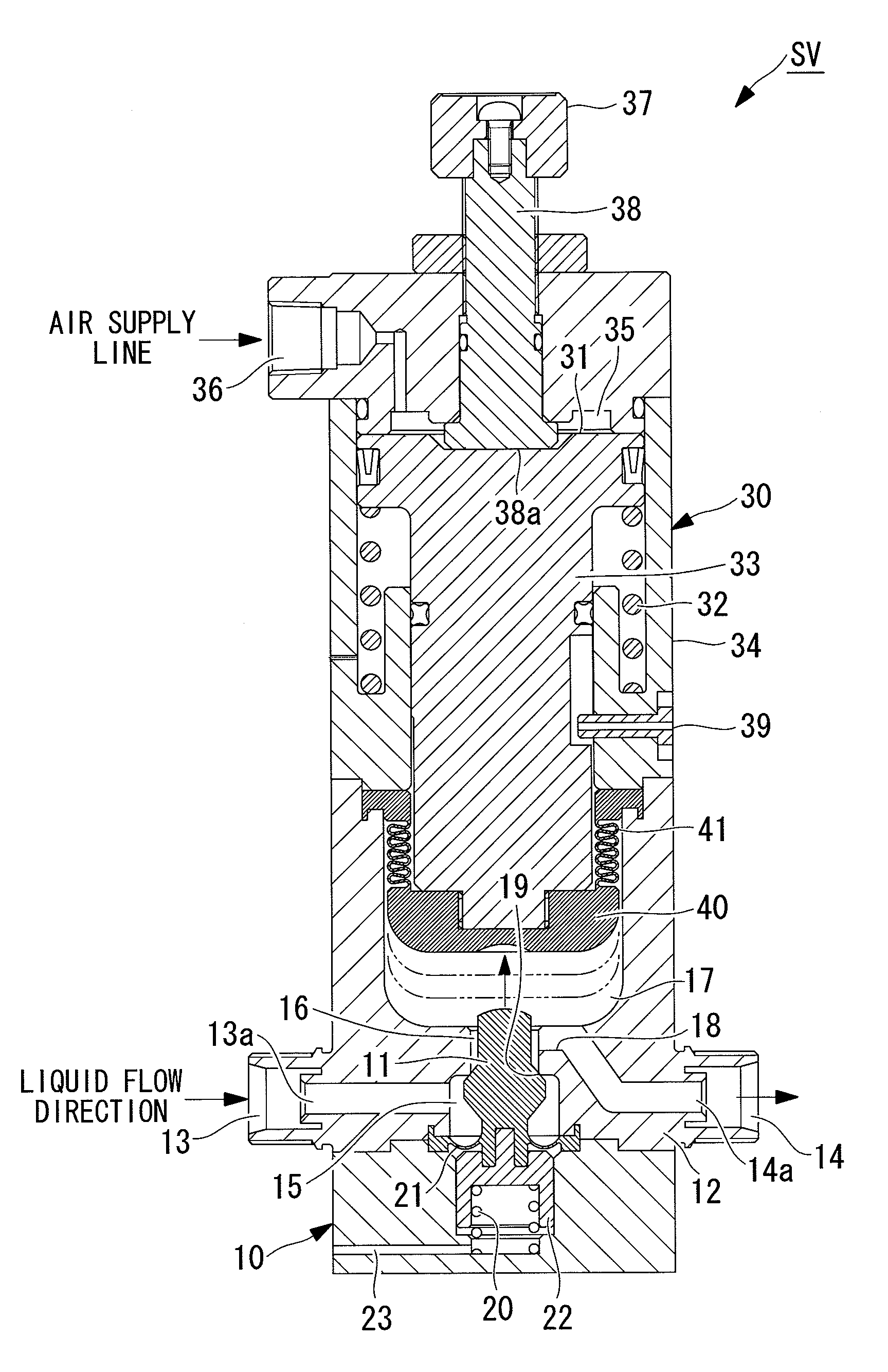
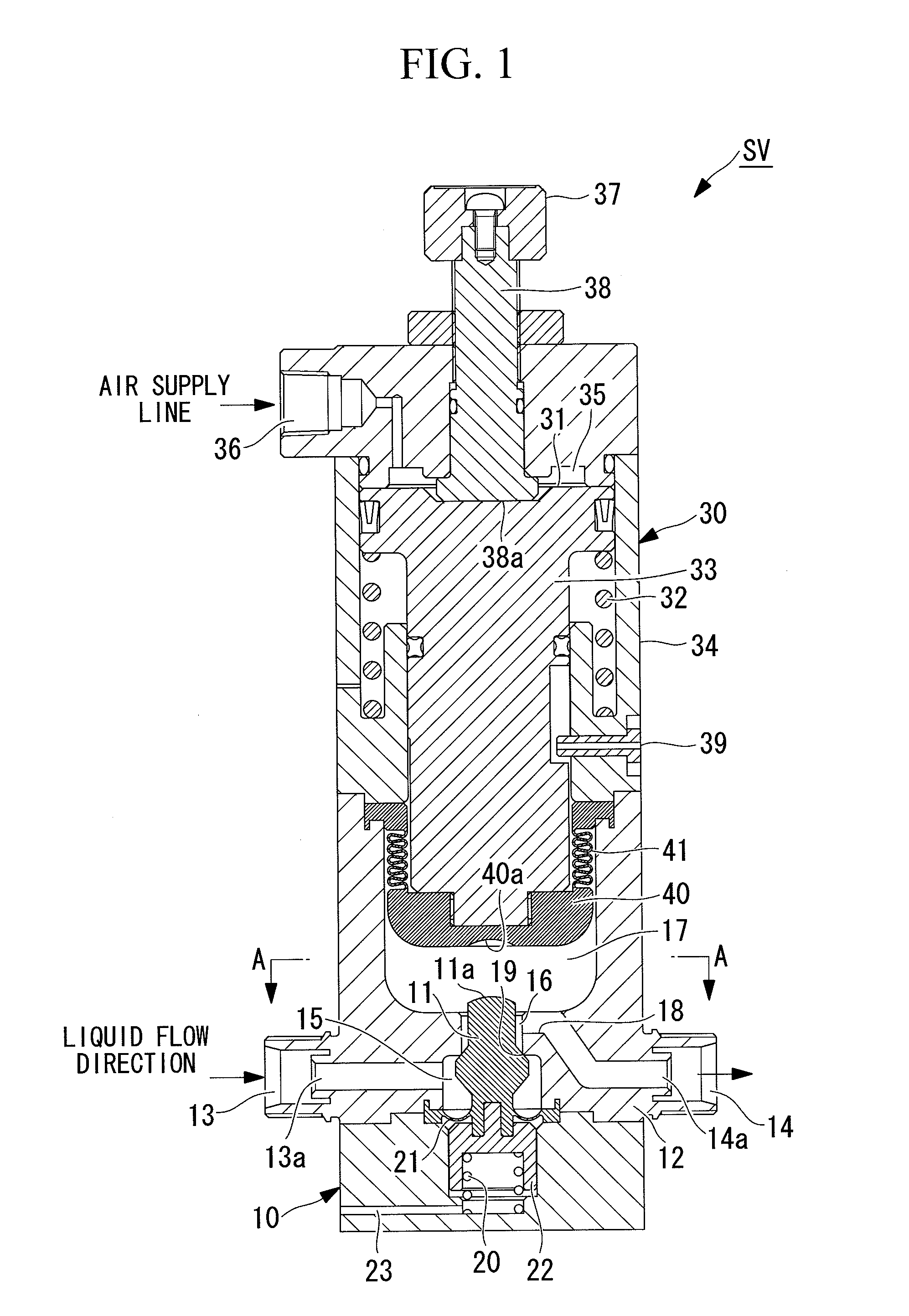
[0027]A suck-back valve SV shown in FIGS. 1 to 6 is configured such that an open / close valve 10 that is disposed in a channel in which liquid such as drug solution flows and that has a suck-back function for preventing leakage while fully closing is integrated with an actuator 30 for the open / close operation. In other words, in the suck-back valve SV, the open / close valve 10, having a valve coil spring (elastic member) 20 that biases a valve piece 11 in the open / close direction, carries out the open / close operation of the valve piece 11 by receiving air pressure (fluid pressure) on the actuator 30 (open / close operation portion) provided with a piston main body 31 and a piston coil spring (piston biasing member) 32 and has a suck-back function that prevents leakage during the fully closing operation.

[0028]Note that FIGS. 1 to 6 show individual states of the su...


PUM


Abstract

A suck-back valve having an open / close valve with a suck-back function is provided. The suck-back valve includes a suck-back chamber formed in a valve internal channel of the open / close valve, a piston shaft portion and an open / close pressuring member to apply pressure to a valve piece, bellows that accommodate the piston shaft portion inside and that are connected to the open / close pressuring member at one end and are supported by a casing at the other end, wherein a two-step operation is performed at the time of a closing operation of the valve piece, including a valve closing operation step in which the piston shaft portion moves to the fully closed position of the valve piece, and a suck-back operation step in which the piston shaft portion and the open / close pressuring member further move from the fully closed position of the valve piece to increase the volume of the suck-back chamber.

Description

BACKGROUND OF THE INVENTION[0001]1. Field of the Invention[0002]The present invention relates to a suck-back valve having a suck-back function that prevents the occurrence of leakage during the fully closing operation of an open / close valve.[0003]This application is based on Japanese Patent Application No. 2008-209762, the content of which is incorporated herein by reference.[0004]2. Description of Related Art[0005]Conventionally, for example, for an open / close valve disposed in a pipeline system for liquid such as drug solution, a separate valve exclusively for “suck-back” has been additionally provided to prevent leakage (dripping of the fluid) that occurs during the fully closing operation. Such a valve exclusively for suck-back operates synchronously with closing operations of the open / close valve, and it is possible to prevent leakage by actuating a diaphragm in a direction that increases the volume of a suck-back chamber, thus sucking liquid on the outlet side to the suck-back...

Claims


Application Information

Patent Timeline
Patent Type & Authority Applications(United States)
IPC IPC(8): F16K31/122
CPCF16K31/1221F16K23/00B05B15/50B05C11/10
Inventor INOUE, ATSUSHI
Owner SURPASS IND
Why Eureka
Try Eureka