Laser diode illuminator device and method for optically conditioning the light beam emitted by the same

a laser diode and light beam technology, applied in the field of laser illuminator devices, can solve the problems of insufficient use of beam symmetry devices, inconvenient use, and inability to meet the requirements of laser diode bar symmetry, etc., to achieve more efficient use, promote higher optical throughput, and compact

Inactive Publication Date: 2010-02-18
INSTITUT NATIONAL D'OPTIQUE
View PDF30 Cites 21 Cited by
  • Summary
  • Abstract
  • Description
  • Claims
  • Application Information

AI Technical Summary

Benefits of technology

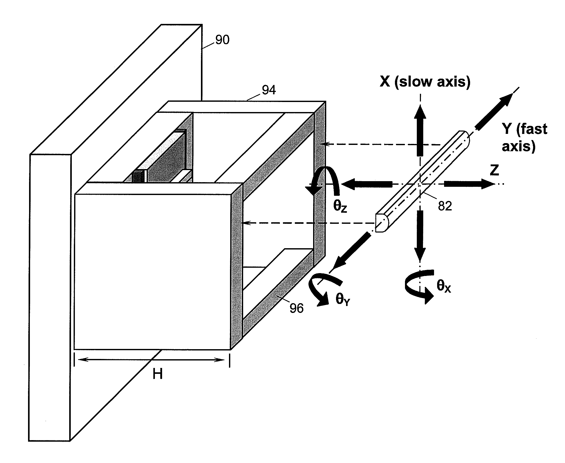
[0017]The second array of optical components consists in a plurality of cylindrical microlenses having appropriate focal lengths for collimation along the slow axis of the beamlets exiting from the micro-optics devices. This scheme for optical conditioning a two-dimensional array of laser beamlets allows for more efficient use of the total light power radiated by a SLDA assembly by promoting higher optical thoughputs. In addition, laser diode illuminators can be made more compact than similar devices of the prior art that make use of bulk lensing for collimation of the beamlets.

Problems solved by technology

These illuminator devices are generally more complex and less affordable than their more conventional counterparts that make use of nonlaser optical sources, so that laser illuminators still find their best use in niche applications that call for highly-demanding illumination characteristics.
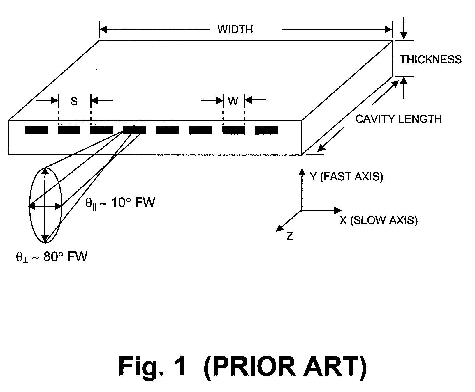
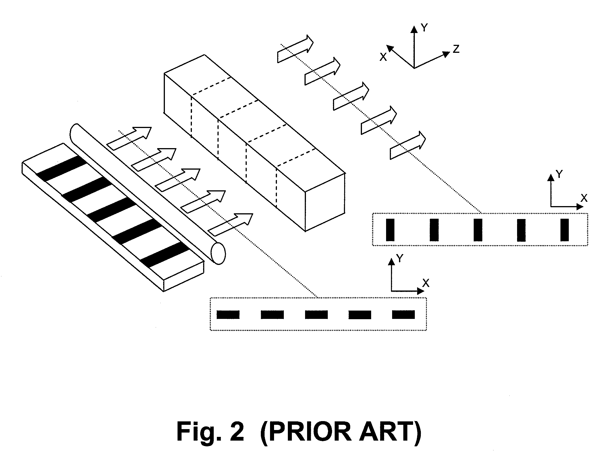
Unfortunately, the linear array of highly-divergent beamlets radiated as a whole by a laser diode bar is totally useless for many applications (including illumination) unless it is passed through suitable beam conditioning optics having a high numerical aperture along the Y axis.
The structural characteristics of laser diode bars along with the quite different beam divergence angles along the fast and slow axes make the optical transformation of the plurality of raw laser beamlets a real challenge, particularly when the laser illumination output beam must meet stringent requirements.
The beam symmetrization devices disclosed in the various patents cited in the preceding paragraph are not well suited for use with laser diode bars having high fill factors because the incoming beamlets must be sufficiently separated from each other to minimize truncation of their irradiance distributions upon entering into the device.
The bars are soldered to the side walls of the grooves, thus resulting in very rugged, monolithic assemblies.
As a consequence, they cannot be used as is for conditioning the laser emission from a SLDA, which takes the form of a two-dimensional array of beamlets having different spacings along the orthogonal fast and slow axes.
Unfortunately, this approach often leads to disappointing results, due to factors such as mismatches between the vertical pitches of the SLDA and of the beam conditioning stack, the overall height of the beam conditioning components that exceeds the array pitch, variations of the array pitch along the whole stack, and possible vertical misalignment of the laser emitters belonging to the same vertical column in the stack.
These factors act together in degrading the overall throughput of the beam conditioning stack while giving a final output laser beam with spatial characteristics that, most of the time, do not fulfill the stringent requirements of several laser illumination applications.

Method used


Image

  • Laser diode illuminator device and method for optically conditioning the light beam emitted by the same
  • Laser diode illuminator device and method for optically conditioning the light beam emitted by the same
  • Laser diode illuminator device and method for optically conditioning the light beam emitted by the same

Examples


Embodiment Construction

[0028]Reference will now be made in detail to the preferred embodiments of the invention. This invention may, however, be embodied in many different forms and should not be construed as limited to the embodiments set forth in the following description. The structure of a laser diode illuminator device 50 built in accordance with a preferred embodiment of the present invention can be better understood by referring to the schematic block diagram shown in FIG. 4. Note that each identical or nearly identical component that is illustrated in the various figures is represented by a like reference numeral. At the heart of the laser illuminator device 50 is a SLDA assembly 52 in which the total number N of stacked laser diode bars is large enough to fulfill the maximum laser output power requirement when the SLDA assembly 52 is driven at its nominal current rating. In practice, the N laser diode bars need not be stacked all in the same array, since the SLDA assembly 52 can be advantageously...


PUM


Abstract

A laser diode illuminator device and a method for optically conditioning the output beam radiated from such a device, so that highly-demanding illumination application requirements that call for high output powers within a specified field of illumination can be addressed. At the heart of the device is a two-dimensional stack of laser diode bars wherein the linear array of beamlets radiated by each laser diode bar is optically conditioned through its passage in a refractive-type micro-optics device followed by a cylindrical microlens. The micro-optics device performs collimation of the linear array of beamlets along the fast axis of the bars, and it also acts as a beam symmetrization device by interchanging the divergences of the laser beamlets along the fast and slow axes. The cylindrical microlens is for collimation of the beamlets along the slow axis. The optical conditioning is performed individually for each linear array of beamlets so that the radiance or brightness of the laser diode illuminator can be optimized while any specified field of illumination can be filled with an excellent uniformity of the radiant intensity.

Description

[0001]This application claims benefit of U.S. 61 / 088,507, filed Aug. 13, 2008, and which application is incorporated herein by reference. To the extent appropriate, a claim of priority is made to the above disclosed application.FIELD OF THE INVENTION[0002]The present invention relates to a laser illuminator device, and more particularly to an illuminator device comprising an optical source made up of a plurality of laser diode bars, the array of beamlets radiated by each laser diode bar being optically conditioned with micro-optics components having their characteristics and positionings optimized for the intended application.BACKGROUND OF THE INVENTION[0003]Laser illuminators are a class of light illumination systems in which at least one laser device acts as the source of optical radiation. These illuminator devices are generally more complex and less affordable than their more conventional counterparts that make use of nonlaser optical sources, so that laser illuminators still fi...

Claims


Application Information

Patent Timeline
Patent Type & Authority Applications(United States)
IPC IPC(8): H01S3/13
CPCG02B27/0966H01S5/4031H01S5/405G02B19/0014G02B19/0057G02B19/0009H01S5/4081
Inventor PARENT, ANDREGRENIER, PAULTAILLON, YVESLABRANCHE, BRUNO
Owner INSTITUT NATIONAL D'OPTIQUE
Why Eureka
Try Eureka