USB locking structure

a technology of usb plug and locking structure, which is applied in the direction of electrical apparatus, connection, coupling device connection, etc., can solve the problems of usb plug being caught and not easily dropping off, and achieve the effect of convenient operation and easy change of the state of the usb plug

Inactive Publication Date: 2010-02-18
CHUFON TECH
View PDF9 Cites 18 Cited by
  • Summary
  • Abstract
  • Description
  • Claims
  • Application Information

AI Technical Summary

Benefits of technology

[0009]After the USB plug is inserted into the USB socket, the locking pieces of the USB socket are respectively engaged in the locking slots of the USB plug to form a semi-locking state (a state in which the USB plug can be released by merely applying a force). Therefore, in the usage of the present invention, the collar slides toward the end of the USB socket disposed with the locking pieces, and each of the locking pieces penetrates the recess of the collar to form a pressing respectively, such that the locking pieces are

Problems solved by technology

Thus, the USB plug is caught and may not easily

Method used


Image

  • USB locking structure
  • USB locking structure
  • USB locking structure

Examples


Embodiment Construction

[0017]In order to make the content of the present invention comprehensible, embodiments accompanied with figures are described in detail below.

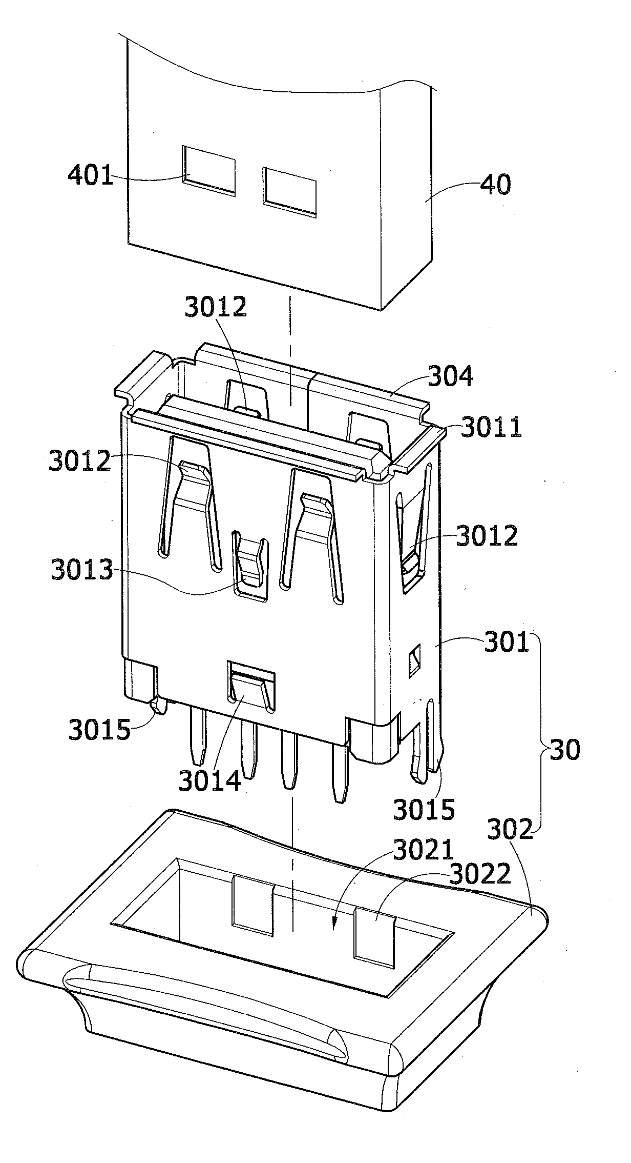
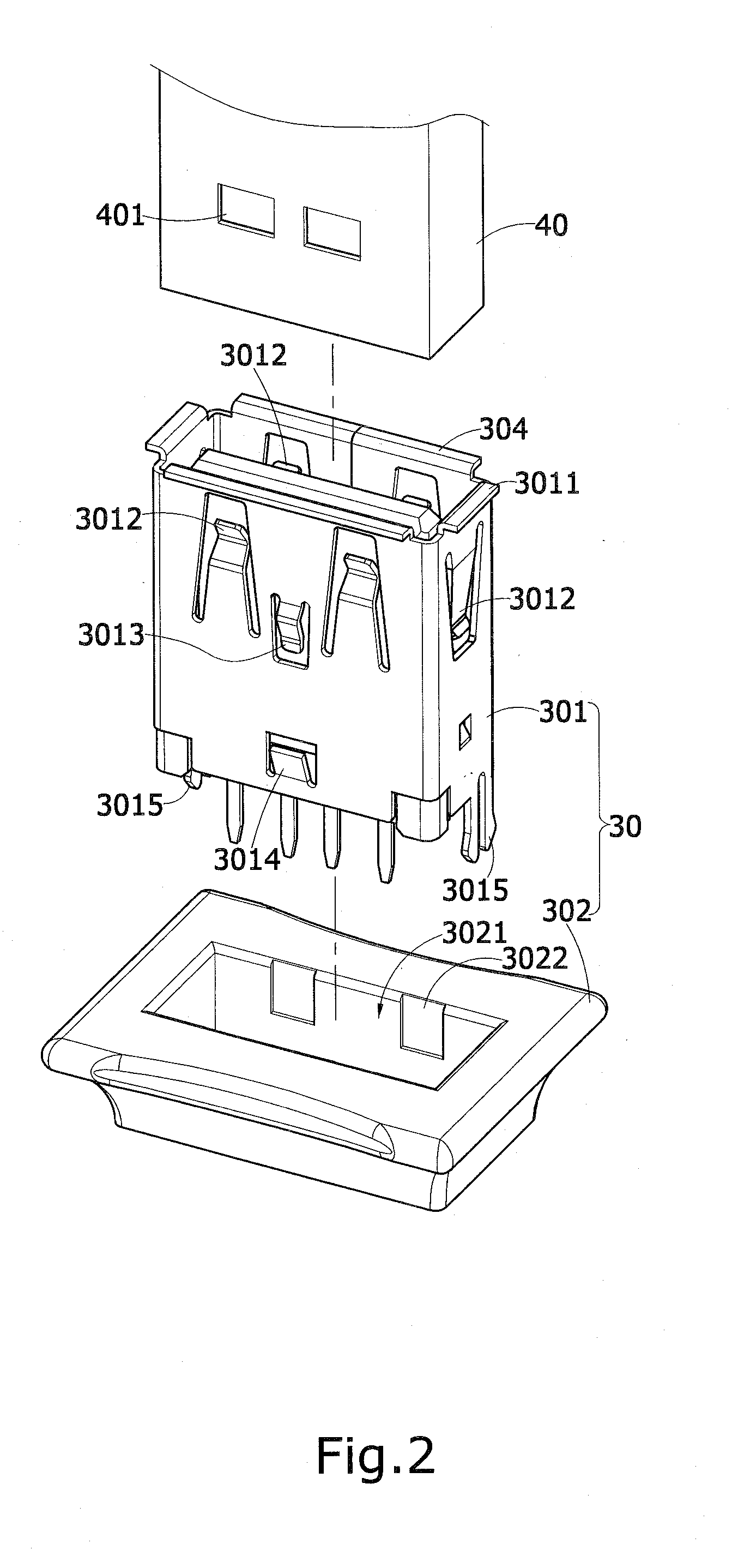
[0018]Referring to FIG. 2, a USB locking structure 30 of the present invention mainly includes a USB socket 301 and a collar 302.

[0019]The USB socket 301 has folded plates 3011 respectively disposed outward and perpendicularly on four edges of an open end thereof, and has a plurality of locking pieces 3012 disposed on each wall. The locking piece 3012 is elastic and V-shaped at a distal end thereof. Furthermore, the USB socket 301 has an urging piece 3013 in an inverted V-shape and a stopper piece 3014 with an up-warping distal end on a corresponding wall. The urging piece and the folded plate have a distance corresponding to the thickness of the collar 302 there-between, and the urging piece 3013 and the stopper piece 3014 have a distance corresponding to the thickness of the collar 302 there-between. In this embodiment, the USB socket 301 o...


PUM


Abstract

A USB locking structure mainly includes a USB socket and a collar. The USB socket is disposed with a plurality of locking pieces. The collar has a rectangular through hole in the middle for being movably fitted on the USB socket. In use, after a USB plug is inserted into the USB socket, the locking pieces are engaged in locking slots of the USB plug. The collar reciprocally slides outside the USB socket so as to press against the locking pieces to catch the USB plug or be separated from the locking pieces to release the USB plug. Thereby, the present invention is quite convenient in operation.

Description

BACKGROUND OF THE INVENTION[0001]1. Field of Invention[0002]The present invention relates to a structure for locking a USB plug, and more particularly to a USB locking structure using a collar to press against locking pieces of a USB socket, so as to catch a USB plug.[0003]2. Related Art[0004]A universal serial bus (USB) commonly used in computers and various expanded equipments for data transmission usually includes a USB socket and a USB plug, and is capable of rapidly accomplishing information linking by inserting the USB plug into the USB socket, so as to perform the data transmission. Currently, the USB is more widely applied in various small household appliances for being electrically connected to the computer, so as to be charged or directly gain power for use.[0005]Referring to FIG. 1, a USB socket 10 has a plurality of locking pieces 101 respectively formed on an upper and a lower face thereof, and a USB plug 20 has locking slots 201 disposed at corresponding positions. The...

Claims


Application Information

Patent Timeline
IPC IPC(8): H01R13/627
CPCH01R13/6273
Inventor WANG, CHIH-CHIANG
Owner CHUFON TECH
Why Eureka
Try Eureka