Suture passer

a technology of suture passer and suture, which is applied in the field of surgical instruments, can solve the problems of inefficient manipulation of suture and suturing instruments, difficulty in actual threading of sutures, and difficulty in actual threading of sutures, and achieve the effect of facilitating the transition of features

Inactive Publication Date: 2010-02-18
KIM ANDREW C +2
View PDF48 Cites 28 Cited by
  • Summary
  • Abstract
  • Description
  • Claims
  • Application Information

AI Technical Summary

Benefits of technology

[0009]In certain embodiments, the suture retaining mechanism includes a deformable tip of the plunger. The deformable tip can include a feature formed at its front, with the front facing the chamber. The feature can be configured to retain the one end of the suture in a closed configuration and release the suture in an open configuration. In certain embodiments, the plunger further includes an actuator mechanism that transmits a force to the deformable tip so as to facilitate transition of the feature from the closed configuration to the open configuration. In certain embodiments, the actuator mechanism includes an actuator rod that provides a pushing force to the deformable tip from rear of the deformable tip so as to deform an area at or about the feature sufficiently to yield the transition. In certain embodiments, the actuator mechanism further includes a hollow rod coupled to the deformable tip, with the hollow rod defining a bore dimensioned to receive the actuator rod and allow axial motion of the actuator rod relative to the hollow rod so as to provide the pushing force to the deformable tip.

Problems solved by technology

Although such desired suture patterns may appear to be simple in isolation, the actual threading of the suture can be difficult and tedious due to the operating site being difficult to access.
Further, the operating site can be small, thereby making manipulation of suture and suturing instruments difficult.
Consequently, use of conventional suturing instruments for certain suturing procedures requires inefficient manipulations of the suture and the instruments.

Method used


Image

  • Suture passer
  • Suture passer
  • Suture passer

Examples


Embodiment Construction

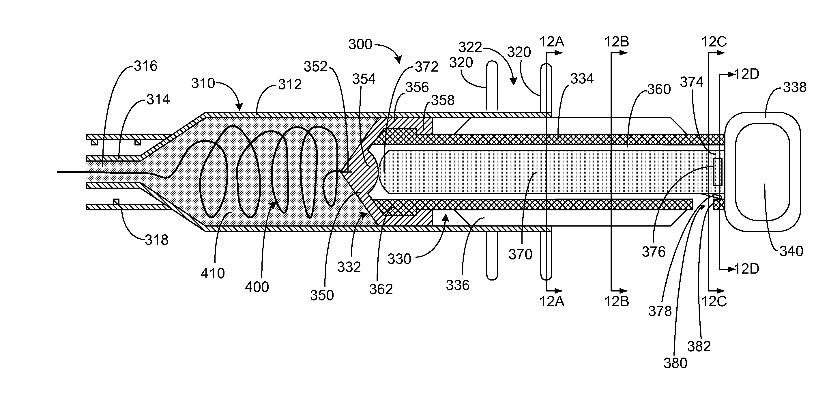
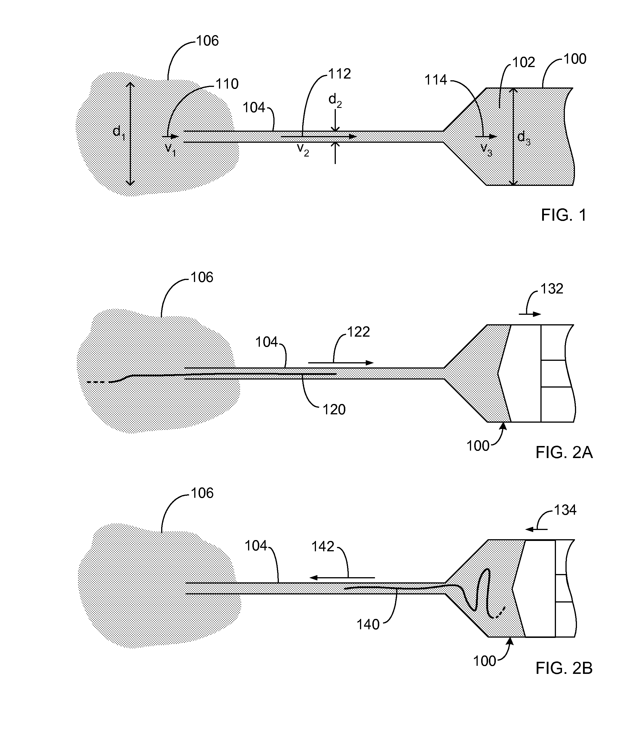
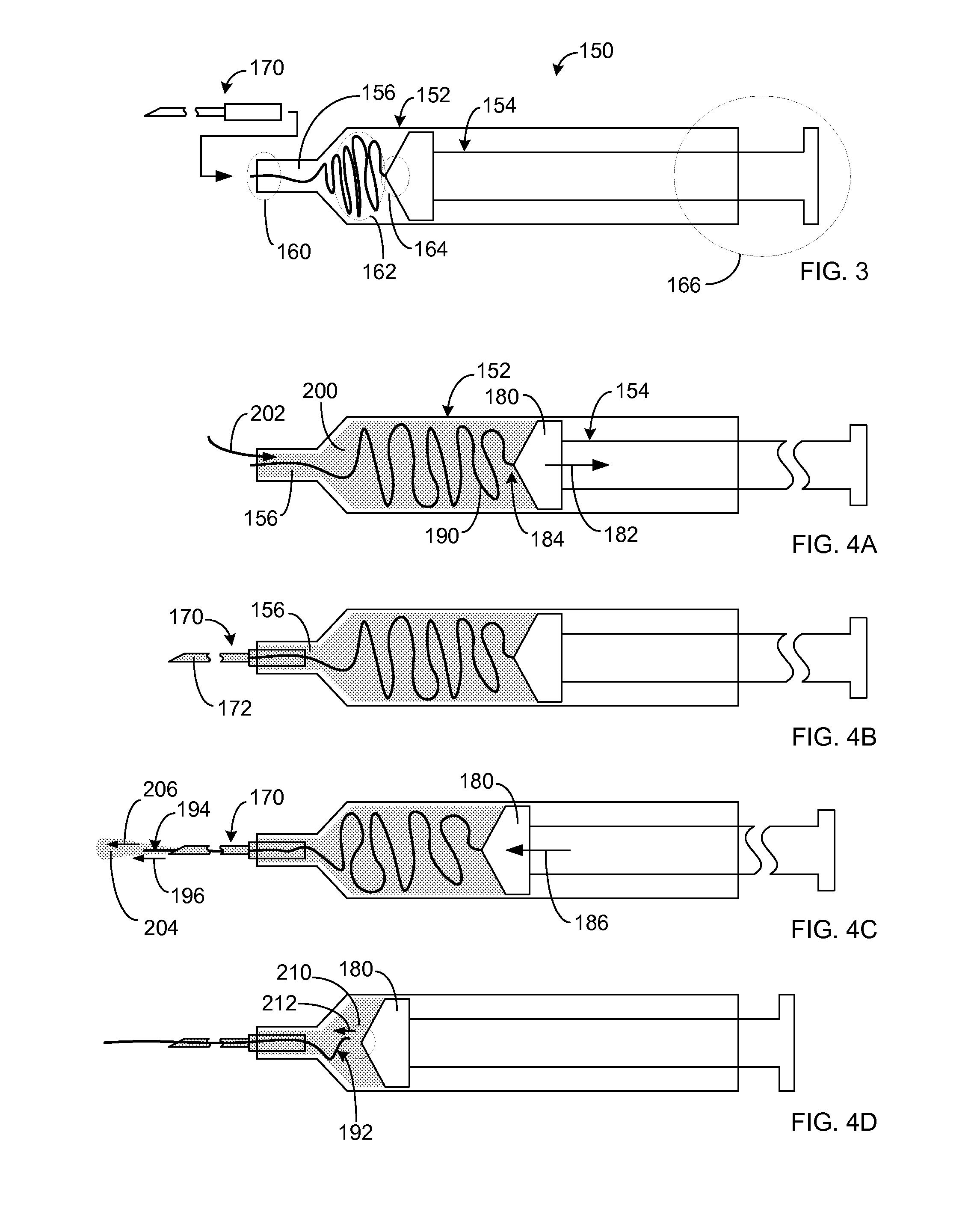
[0054]The present disclosure generally relates to the field of surgical instruments, and more particularly, to devices and methods for passing sutures during surgical procedures. In many surgeries, various suturing procedures may need to be performed in locations that are relatively difficult to access and / or work in. In such surgical procedures, use of hydrodynamic suture passers can overcome or mitigate at least some of such difficulties. Additional details about such suture passers can be obtained from, for example, U.S. patent application Ser. No. 10 / 614,653 titled “Hydrodynamic Suture Passer,” filed Jul. 7, 2003, and U.S. patent application Ser. No. 10 / 883,742 titled “Hydrodynamic Suture Passer,” filed Jul. 6, 2004, each of which is incorporated herein by reference in its entirety.

[0055]As described herein, one or more features of the present disclosure can facilitate easier suturing procedures involving manipulation of sutures via fluid movements. It will be understood that su...


PUM


Abstract

Disclosed are devices and methods relating to a suture passer that passes suture efficiently via motion of fluid in and out of the suture passer. In certain embodiments, the suture passer includes a syringe-like barrel and a plunger for drawing and expelling fluid from the barrel. A suture can be disposed within the barrel, and one end of the suture can be releasably secured to a portion of the plunger. In certain embodiments, the suture end can be releasably secured to a tip portion of the plunger. Various examples of suture releasing mechanisms and actuations of such mechanisms are disclosed. Also disclosed are examples of how such releasably secured sutures can be assembled and packaged into pre-loaded suture passer devices. Also disclosed are examples of suturing operations that can be achieved easier and quicker by use of such suture passer devices.

Description

RELATED APPLICATION[0001]This application claims priority benefit of U.S. Provisional Patent Application No. 61 / 136,119 filed Aug. 13, 2008, titled “HYDRODYNAMIC SUTURE PASSER,” which is incorporated herein by reference in its entirety.BACKGROUND[0002]1. Field[0003]The present disclosure generally relates to the field of surgical instruments, and more particularly, to devices and methods for passing sutures during surgical procedures.[0004]2. Description of the Related Art[0005]In many surgical procedures, a need to immobilize a tissue arises. For example, a torn ligament or tendon may need to be re-attached to a bone. Such re-attachment can be achieved by using a suture to hold down the tissue to a desired location such as a bone. The suture can be threaded through one or more locations on the tissue so as to form a desired pattern.[0006]Although such desired suture patterns may appear to be simple in isolation, the actual threading of the suture can be difficult and tedious due to...

Claims


Application Information

Patent Timeline
Patent Type & Authority Applications(United States)
IPC IPC(8): A61B17/10
CPCA61B17/0469A61B2017/061A61B2017/06052A61B17/0482
Inventor KIM, ANDREW C.VAN ELDEREN, RONALDCHANG, JAMES W.
Owner KIM ANDREW C
Why Eureka
Try Eureka