Rear propulsion system with lateral air inlets for an aircraft with such system

a propulsion system and rear propulsion technology, applied in the direction of machines/engines, mechanical apparatus, transportation and packaging, etc., can solve the problems of many problems of mechanical installation and aerodynamic integration, and the apu system comes from the mass that it represents, and the thrust balance is not always optimal,

Active Publication Date: 2010-02-25
AIRBUS OPERATIONS (SAS)
View PDF7 Cites 23 Cited by
  • Summary
  • Abstract
  • Description
  • Claims
  • Application Information

AI Technical Summary

Benefits of technology

[0020]In order not to generate aerodynamic penalty when the auxiliary jet engine is not in use, each lateral air intake is provided with closure means having a closed position in which the corresponding air intake is masked on the fuselage external surface, ensuring the continuity of this external surface, and at least an opened position in which the a

Problems solved by technology

While respecting the certification criteria and the operational constraints, the choice of the number and the characteristics of the engines is the result of compromises implying the desired, or required, performances of the aircraft in its various flying phases and in the various probable operating situations of the engines.
However, for industrial and operational reasons, the various engines of aircraft in commercial exploitation are of the same model which has advantages in the field of the engines maintenance but does not present necessarily an optimum in term of thrust b

Method used


Image

  • Rear propulsion system with lateral air inlets for an aircraft with such system
  • Rear propulsion system with lateral air inlets for an aircraft with such system
  • Rear propulsion system with lateral air inlets for an aircraft with such system

Examples


Embodiment Construction

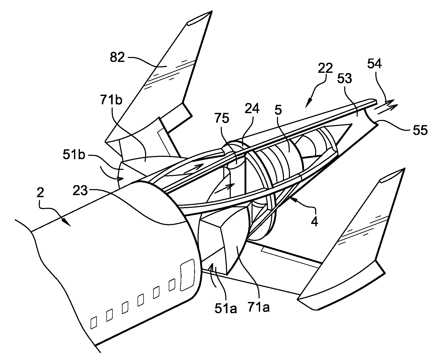
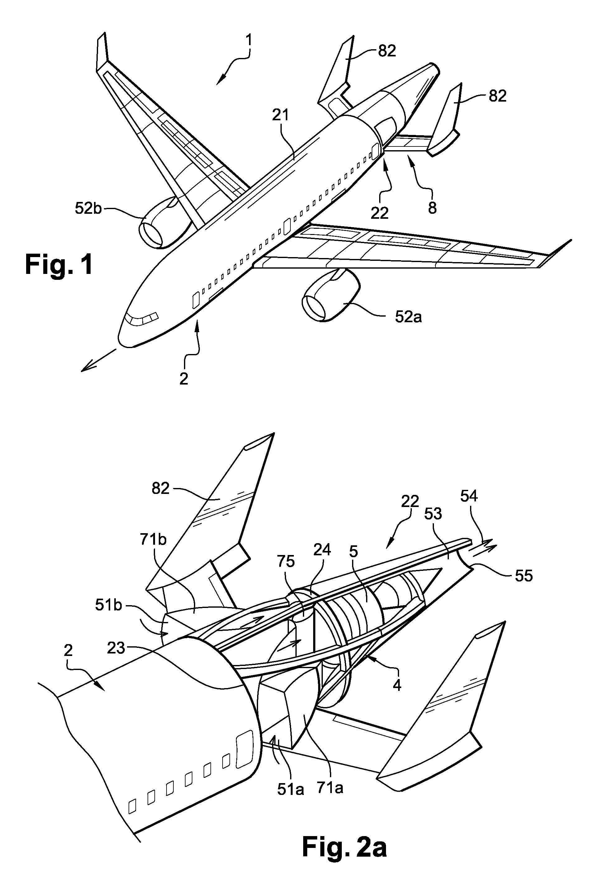
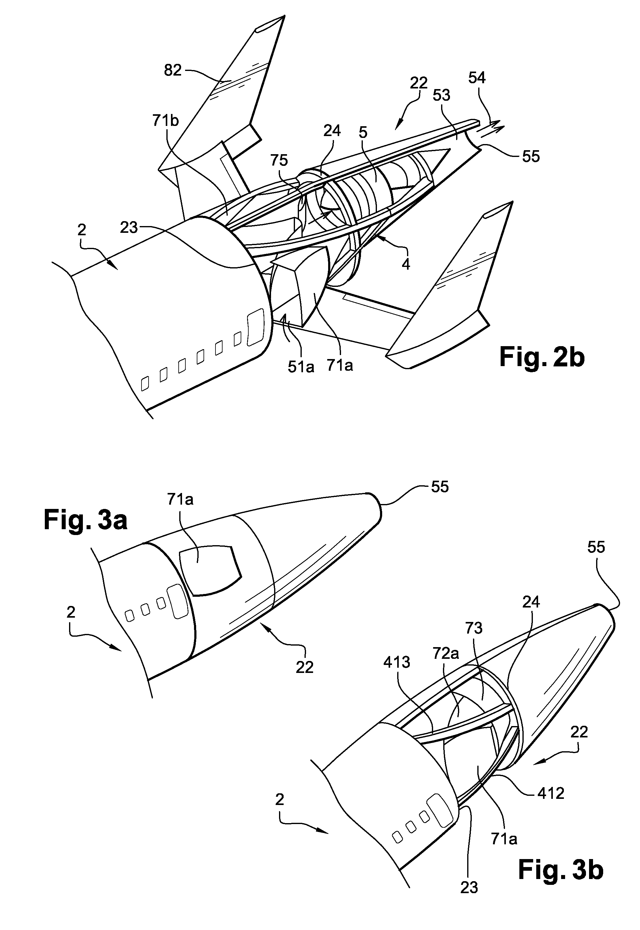
[0035]On an aircraft 1, shown in FIG. 1, according to the aspects of the disclosed embodiments a fuselage 2, in a known way, comprises a substantially cylindrical central part 21 which is continued by a rear part 22 of the fuselage known as a tail cone, rearwards along the displacement direction (materialized by an arrow directed forwards on FIG. 1) of the aircraft during flight, whose sections decrease gradually from a section of the cylindrical part towards a final, relatively small, rear section.

[0036]In the description of the embodiments disclosed herein, it will be indicated by “front” and “rear” the aircraft forward direction along the flight displacement direction and respectively backward along the direction opposed to the flight displacement direction.

[0037]More particularly, in the auxiliary propulsive system according to the aspects of the disclosed embodiments, the final section corresponds to an exit section 55 of a nozzle 53 of an auxiliary jet engine 5 fixed within th...


PUM


Abstract

A propulsive system for an aircraft including an auxiliary jet engine is integrated within a tail cone of a fuselage. Lateral air intakes include each one a scoop movable between a closed position and an opened position are associated with aerodynamic channels to supply with air the auxiliary jet engine. The aerodynamic channels meet at a common channel including a movable flap to balance air flows coming from the air intakes when the operation is not symmetrical.

Description

CROSS-REFERENCE TO RELATED APPLICATIONS[0001]This application claims priority to French Application No. 08 51344 filed on 29 Feb. 2008, the disclosure of which is incorporated by reference herein in its entirety.BACKGROUND[0002]1. Field[0003]The disclosed embodiments generally relate to the field of aircraft powered by jet engines such as transport civil aircraft.[0004]More particularly the disclosed embodiments relate to an aircraft including at least an engine installed into the fuselage tail section in order to be used only in certain running phases of the aircraft on the ground or in flight.[0005]2. Brief Description of Related Developments[0006]For safety reasons and in order to fulfill the certification lawful requirements, the transport aircraft comprise two or several engines in order to survive to engine failure cases during the various flying, takeoff, cruising or approach and landing phases.[0007]While respecting the certification criteria and the operational constraints,...

Claims


Application Information

Patent Timeline
IPC IPC(8): B64D41/00F02K1/06F02C6/00
CPCB64D33/02B64D2033/0213B64D41/00
Inventor CAZALS, OLIVIER
Owner AIRBUS OPERATIONS (SAS)
Why Eureka
Try Eureka