Diaphragm pump and method for delivering fine-grain powder with the aid of a diaphragm pump

a diaphragm pump and diaphragm technology, which is applied in the direction of conveyors, liquid fuel engines, positive displacement liquid engines, etc., can solve the problems of high gas volume flows, steep increase in surface adhesion forces, and inability to convey fine powders with less than 150 m particle size, etc., to achieve the effect of cleaning the conveyance chamber

Active Publication Date: 2016-05-24
MASCHFAB REINHAUSEN GEBR SCHEUBECK GMBH & CO KG
View PDF60 Cites 4 Cited by
  • Summary
  • Abstract
  • Description
  • Claims
  • Application Information

AI Technical Summary

Benefits of technology

[0013]The inlet valve of the diaphragm pump acts as a non-return valve, such that the supplied gas, for example air, can stream out of the outlet valve only in the conveyance direction of the diaphragm pump. The additional introduction of gas continuously ensures optimal flow conditions in the working volume of the diaphragm pump and avoids powder deposits in the conveyance chamber.
[0017]An effective cleaning of the conveyance chamber by means of the supplied gas is achieved, when the gas supply has a compressor for generating a pulsating volume flow of the gas.

Problems solved by technology

The conveyance of fine powders with a particle size of less than 150 μm is scarcely possible with known pumps.
The steep increase in the surface adhesion forces impairs the conveyance of such small particles.
High gas volume flows are, however, disadvantageous in many subsequent working processes, such as, for example, in plasma-coating processes or laser-coating processes.
When using a diaphragm pump for the conveyance of a powder / gas mixture, for example, containing fine-grained powders, the flow speed in the working volume of the conveyance chamber of the diaphragm pump is typically insufficient to exhale the entire amount of powder through the outlet valve.
Consequently, increasing accumulations of powder form inside the conveyance chamber of the diaphragm pump as the operation of the diaphragm pump goes on, thus, reducing the suction power and eventually blocking the diaphragm pump.
A blockage of the diaphragm pump cannot be avoided by increasing the pumping power.
It has also been found that blockages occur in the region of the outlet valves during the conveyance of fine-grained powders.
Mitigation of these ‘problem zones’ in the conveyance chamber by increasing the flow rate of a diaphragm pump with a given working range, from a particular negative pressure on the suction side and a particular pressure at the pressure side, is not readily possible.

Method used


Image

  • Diaphragm pump and method for delivering fine-grain powder with the aid of a diaphragm pump
  • Diaphragm pump and method for delivering fine-grain powder with the aid of a diaphragm pump

Examples


Embodiment Construction

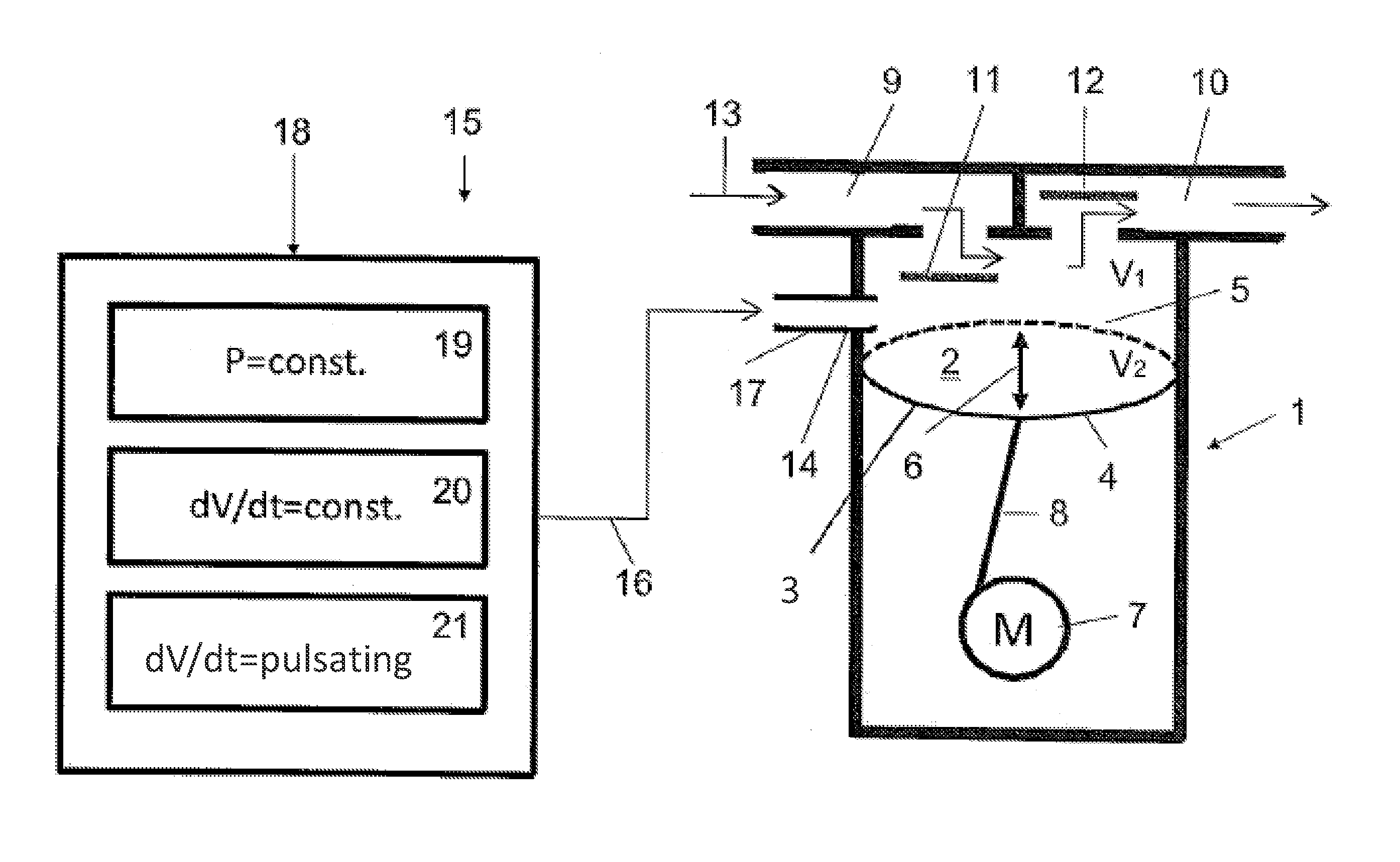
[0025]At the outset, it should be appreciated that like drawing numbers on different drawing views identify identical, or functionally similar, structural elements of the invention. While the present invention is described with respect to what is presently considered to be the preferred aspects, it is to be understood that the invention as claimed is not limited to the disclosed aspects.

[0026]Furthermore, it is understood that this invention is not limited to the particular methodology, materials and modifications described and, as such, may, of course, vary. It is also understood that the terminology used herein is for the purpose of describing particular aspects only, and is not intended to limit the scope of the present invention, which is limited only by the appended claims.

[0027]Unless defined otherwise, all technical and scientific terms used herein have the same meaning as commonly understood to one of ordinary skill in the art to which this invention belongs. Although any me...


PUM


Abstract

The invention relates to a diaphragm pump having a delivery space, which encloses a working volume, at least one deflectable diaphragm, which can be moved into a suction position and a pump position, an inlet valve arranged on a suction side of the diaphragm pump and an outlet valve arranged on the pressure side of the diaphragm pump. In order to make it possible to deliver fine-grain powder, for example, non-flowable powders having particle sizes of 0.01 μm to 100 μm, using a diaphragm pump, it is proposed that a gas feed for introducing a gas into the delivery space be arranged at the delivery space. In addition, the invention relates to a method for delivering fine-grain powder.

Description

CROSS-REFERENCE TO RELATED APPLICATIONS[0001]This application is filed under 35 U.S.C. §120 and §365(c) as a continuation of International Patent Application PCT / EP2012 / 055613, filed Mar. 29, 2012, which application claims priority from German Patent Application No. 10 2011 017 277.7, filed Apr. 15, 2011, German Patent Application No. 10 2011 100 378.2, filed May 3, 2011 and German Patent Application No, 10 2011 052 432.0, filed Aug. 5, 2011, which applications are incorporated herein by reference in their entireties.FIELD OF THE INVENTION[0002]The invention relates to a method for conveying fine-grained powders by means of a diaphragm pump. The diaphragm pump includes a conveyance chamber, which encloses a working volume and at least one deflectable diaphragm, which can be brought into a suction position and a pressure position. The diaphragm pump further includes an inlet valve arranged at its suction side and an outlet valve arranged at its pressure side.BACKGROUND OF THE INVENTI...

Claims


Application Information

Patent Timeline
Patent Type & Authority Patents(United States)
IPC IPC(8): B65G53/66F04B43/00F04B15/02F04B43/02B05B7/14
CPCF04B43/02B05B7/144B05B7/1459F04B15/02F04B43/0054F04B43/0081F04B45/047F04B53/10F04B2205/501F05B2210/10Y10S417/00
Inventor NETTESHEIM, STEFANALBRECHT, ANDREASMENATH, JOHANN
Owner MASCHFAB REINHAUSEN GEBR SCHEUBECK GMBH & CO KG
Why Eureka
Try Eureka