Door lock

a door lock and lock body technology, applied in the field of door locks, can solve the problems of affecting the operation of the lock, imposing a great force between the striker plate and the bolt, and the force conveyed from the actuator to the lock can be quite great, so as to reduce the electrical energy needed

Active Publication Date: 2010-02-25
ABLOY OY
View PDF8 Cites 2 Cited by
  • Summary
  • Abstract
  • Description
  • Claims
  • Application Information

AI Technical Summary

Benefits of technology

[0008]The objective of the invention is to reduce the electrical energy needed by a lock body to control the lock and, simultaneously, use a lower-power actuator such as a solenoid. It is desired that operation of the lock is re...

Problems solved by technology

If the solenoid/actuator is too weak in power, this will cause disruptions in lock operation such as unwanted locked states.
This may impose a great force between the striker plate...

Method used


Image

  • Door lock
  • Door lock
  • Door lock

Examples


Embodiment Construction

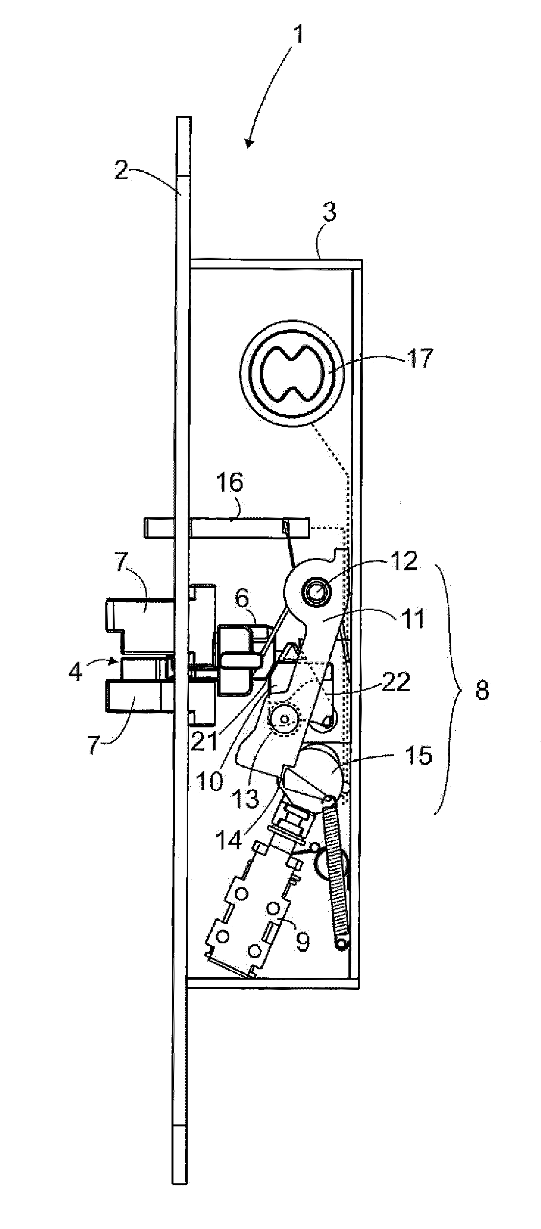
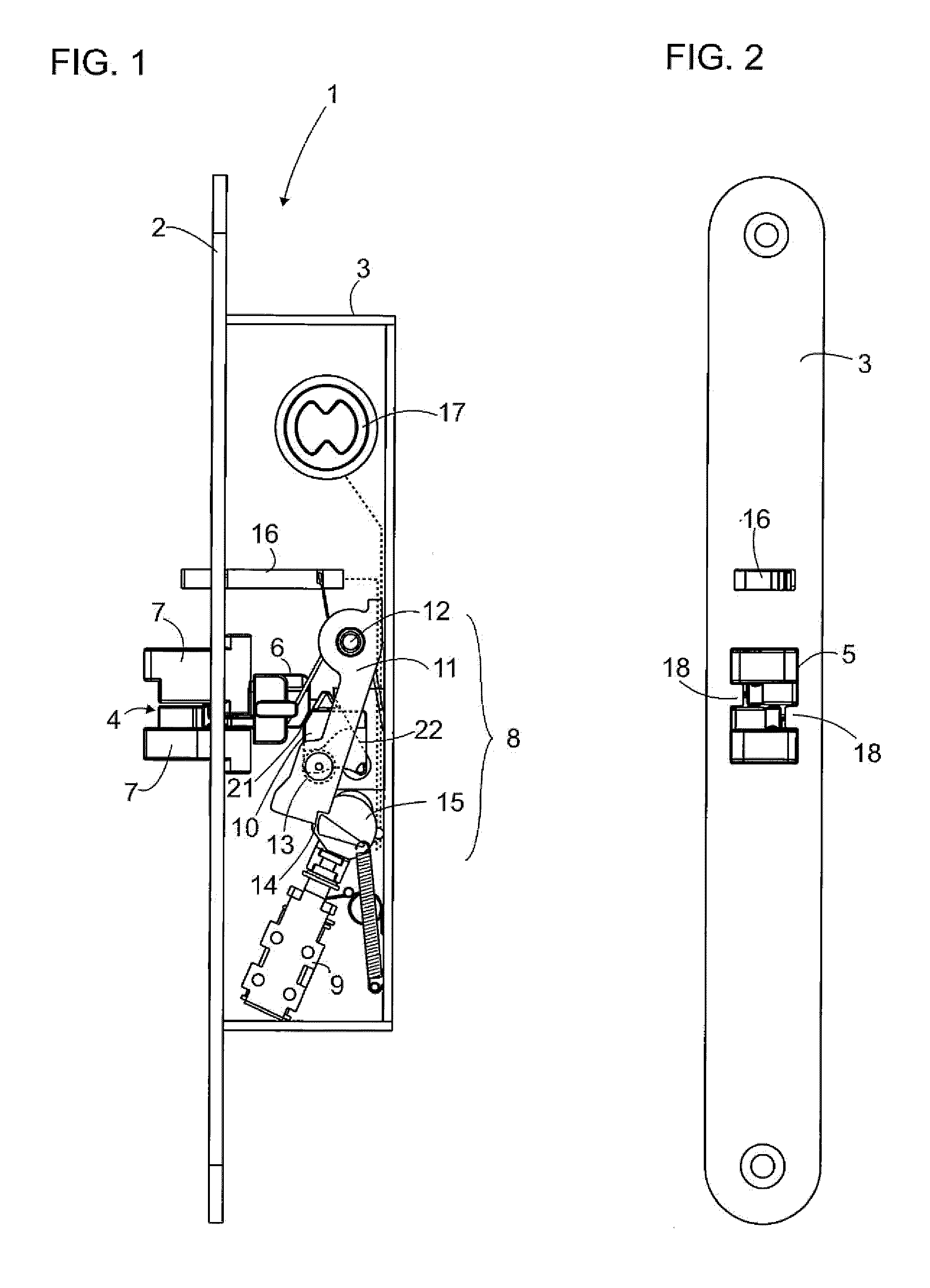
[0020]FIG. 1 illustrates an example of a door lock 1 according to the invention. The door lock comprises a lock body 3 fitted with a front plate 2; the lock body has a dual-action bolt 4 that can be moved with reciprocal linear motion between a withdrawn position and a locking position protruding out from the lock body through the bolt opening 5 (FIG. 2) in the front plate 2. The bolt 4 comprises a body part 6, and in the embodiment of FIG. 1, two bolt pieces 7. The bolt 4 is spring-loaded towards said protruding position. The door lock 1 further comprises deadbolting means 8 that can be moved to a deadbolting position in which they prevent the dual-action bolt from being moved from the protruding position to the withdrawn position in the lock body 3. The lock of this embodiment also comprises a solenoid 9 for controlling the deadbolting means.

[0021]The door lock usually also comprises other control means for controlling the deadbolting means. The lock may have an auxiliary bolt 16 ...


PUM


Abstract

This invention relates to a door lock comprising a lock body (3) fitted with a front plate and a bolt (4). The transfer of external force to the locking piece (5) in the lock body is reduced. The reduction of external force is arranged in two stages of transmission. At the first stage of transmission, the transmitted force is reduced using a wedge part (10) that is in force transmission contact with a lever (11). The second stage of transmission constitutes the lever.

Description

FIELD OF TECHNOLOGY[0001]This invention relates to a door lock comprising a lock body fitted with a front plate and a dual-action bolt. The bolt can be moved with reciprocal linear motion between a withdrawn position and a locking position protruding out from the lock body.PRIOR ART[0002]An electrically controlled door lock often uses a solenoid or other actuator to control deadbolting means in the lock as to lock the bolt in the deadbolting position. In the deadbolting position, the bolt is out; in other words, protruding out from the lock body. The solenoid is also used to release the deadbolting means from the deadbolting position, which allows the bolt to move into the lock body to the withdrawn position.[0003]In prior art solutions, the solenoid or other actuator is functionally linked to a deadbolting piece that can be moved so that it locks the bolt in the deadbolting position. In a typical implementation, the deadbolting piece is linked to the solenoid shaft, and a spring is...

Claims


Application Information

Patent Timeline
IPC IPC(8): E05C1/12E05B65/10E05C1/08E05B47/06
CPCE05B15/102E05B2047/0065E05B47/0607E05B47/0002Y10T292/0994Y10T292/096Y10T292/0908Y10T292/097Y10T292/1021E05C5/00
Inventor HELISTEN, MIKA
Owner ABLOY OY
Why Eureka
Try Eureka