

Electrolytic process for the production of metallic copper and apparatus therefor
- Summary
- Abstract
- Description
- Claims
- Application Information
AI Technical Summary
Benefits of technology
Problems solved by technology
Method used
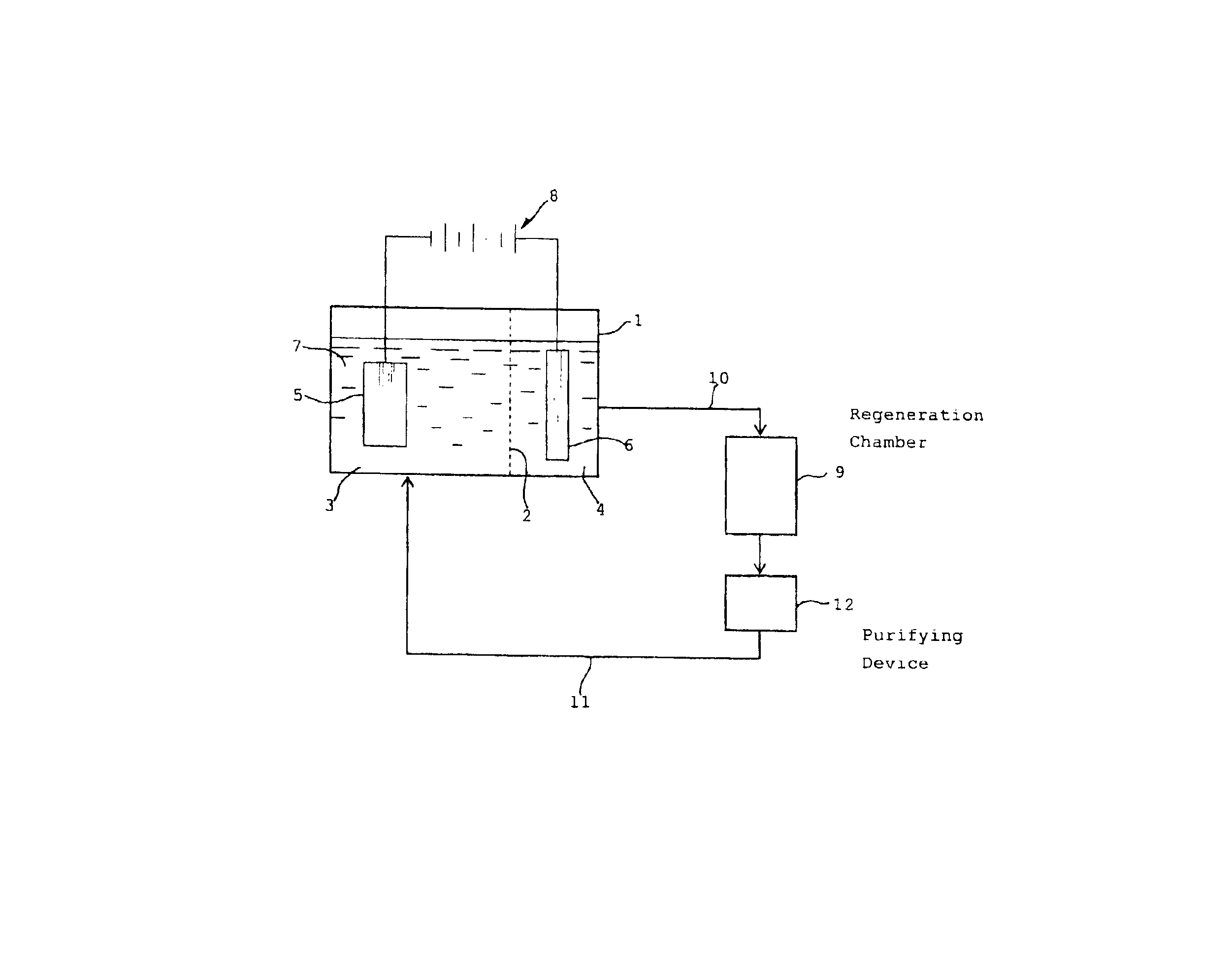
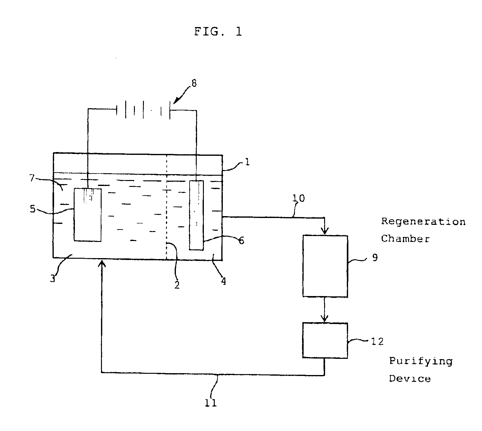
Image

Examples
example 1
An ammoniacal alkaline electrolyte solution containing 31.8 g / L of Cu(I) ions (diammine cuprous ions), 5.0 mol / L of NH3 and 1 mol / L of ammonium sulfate was charged in an airtight electrolytic cell whose inside was separated by a filter cloth into a cathode chamber in which a copper cathode was disposed and an anode chamber in which a platinum anode was disposed. The inside space of the electrolytic cell had been deaerated and maintained in a nitrogen atmosphere. Electrolysis was performed at 25° C. by applying a direct current (current density: 500 A / m2) to the cathode and anode. Metallic copper was found to be formed on the cathode with current efficiency of 98% based on the theoretical yield, while copper(II) ions (tetrammine cupric ions) were formed on the anode with current efficiency of 99% based on the theoretical yield. The electrolyte in the cathode chamber was colorless and transparent, while that in the anode chamber turned blue. The consumed electric power was 190 kWh / t w...
example 2
An ammoniacal alkaline electrolyte solution containing 25.2 g / L of Cu(I) ions, 6.3 g / L of Cu(II) ions, 5.0 mol / L of NH3 and 1 mol / L of ammonium sulfate was prepared using 28% aqueous ammonia. The ammoniacal alkaline electrolyte solution was charged in an airtight electrolytic cell whose inside was separated by a filter cloth into a cathode chamber in which a copper cathode was disposed and an anode chamber in which a platinum anode was disposed. The inside space of the electrolytic cell had been deaerated and maintained in a nitrogen atmosphere. Electrolysis was performed at 25° C. by applying a direct current (current density: 500 A / m2) to the cathode and anode. Metallic copper was found to be formed on the cathode with current efficiency of 78% based on the theoretical yield, while copper(II) ions were formed on the anode with current efficiency of 96% based on the theoretical yield. When the above procedure was repeated in the same manner as described except that the electrolysis...
example 3
In an aqueous solution containing 5.0 mol / L of NH3, 0.25 mol / L of cupric sulfate and 1 mol / L of ammonium sulfate, a printed wiring board having metallic copper wirings was immersed. The solution was stirred for 8 hours under a nitrogen atmosphere to obtain a substantially colorless solution (ammoniacal alkaline solution containing diammine cuprous ions) which was used as a feedstock.
An airtight electrolytic cell was separated by a permeable filter cloth into a cathode chamber and an anode chamber. A copper plate cathode (4 cm×4 cm) and a platinum plate anode (4 cm×4 cm) were disposed in the cathode chamber and the anode chamber, respectively, with one of the both surfaces of each of the cathode and anode plates being in contact with the inside wall of the cell so that only the other surface of each plate being utilized. The inside space of the electrolytic cell had been deaerated and maintained in a nitrogen atmosphere. An anolite solution (200 ml) which was an aqueous solution cont...
PUM
| Property | Measurement | Unit |
|---|---|---|
| Acidity | aaaaa | aaaaa |
| Metallic bond | aaaaa | aaaaa |
Abstract
Description
Claims
Application Information