In-vehicle system

a technology of in-vehicle system and electric energy storage, which is applied in the direction of battery/fuel cell control arrangement, transportation and packaging, etc., can solve the problems of reducing the amount of stored electric energy in the auxiliary-device battery, and affecting the operation of the device (auxiliary device), so as to reduce the amount of stored electric energy and facilitate the time required

Pending Publication Date: 2022-03-03
TOYOTA JIDOSHA KK
View PDF0 Cites 3 Cited by
  • Summary
  • Abstract
  • Description
  • Claims
  • Application Information

AI Technical Summary

Benefits of technology

[0004]By the way, it is possible to easily secure a time required for rewriting the software of the electronic control device (ECU) when an electric power switch (e.g., IG switch) of the vehicle is in an OFF state, so that it is desirable that the in-vehicle system is constructed to enable the software to be rewritable when the electric power switch is in the OFF state as well as when the electric power switch of the vehicle is in an ON state. However, in that case, where the rewriting of the software of the electronic control device (ECU) is executed with use of an electric power supplied from an auxiliary-device battery in the OFF state of the electric power switch, an amount of electric energy stored in the auxiliary-device battery is reduced so that there is a risk that the reduction of the stored electric energy amount could affect operations of devices (auxiliary devices) to which the electric power is to be supplied from the auxiliary-device battery.

Problems solved by technology

However, in that case, where the rewriting of the software of the electronic control device (ECU) is executed with use of an electric power supplied from an auxiliary-device battery in the OFF state of the electric power switch, an amount of electric energy stored in the auxiliary-device battery is reduced so that there is a risk that the reduction of the stored electric energy amount could affect operations of devices (auxiliary devices) to which the electric power is to be supplied from the auxiliary-device battery.

Method used


Image

  • In-vehicle system
  • In-vehicle system
  • In-vehicle system

Examples


embodiment

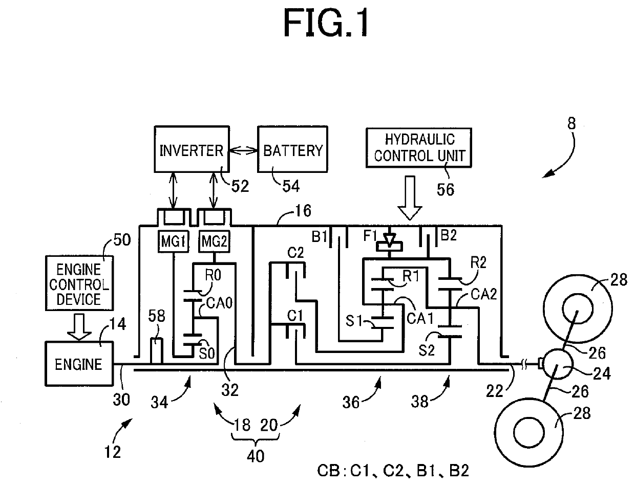
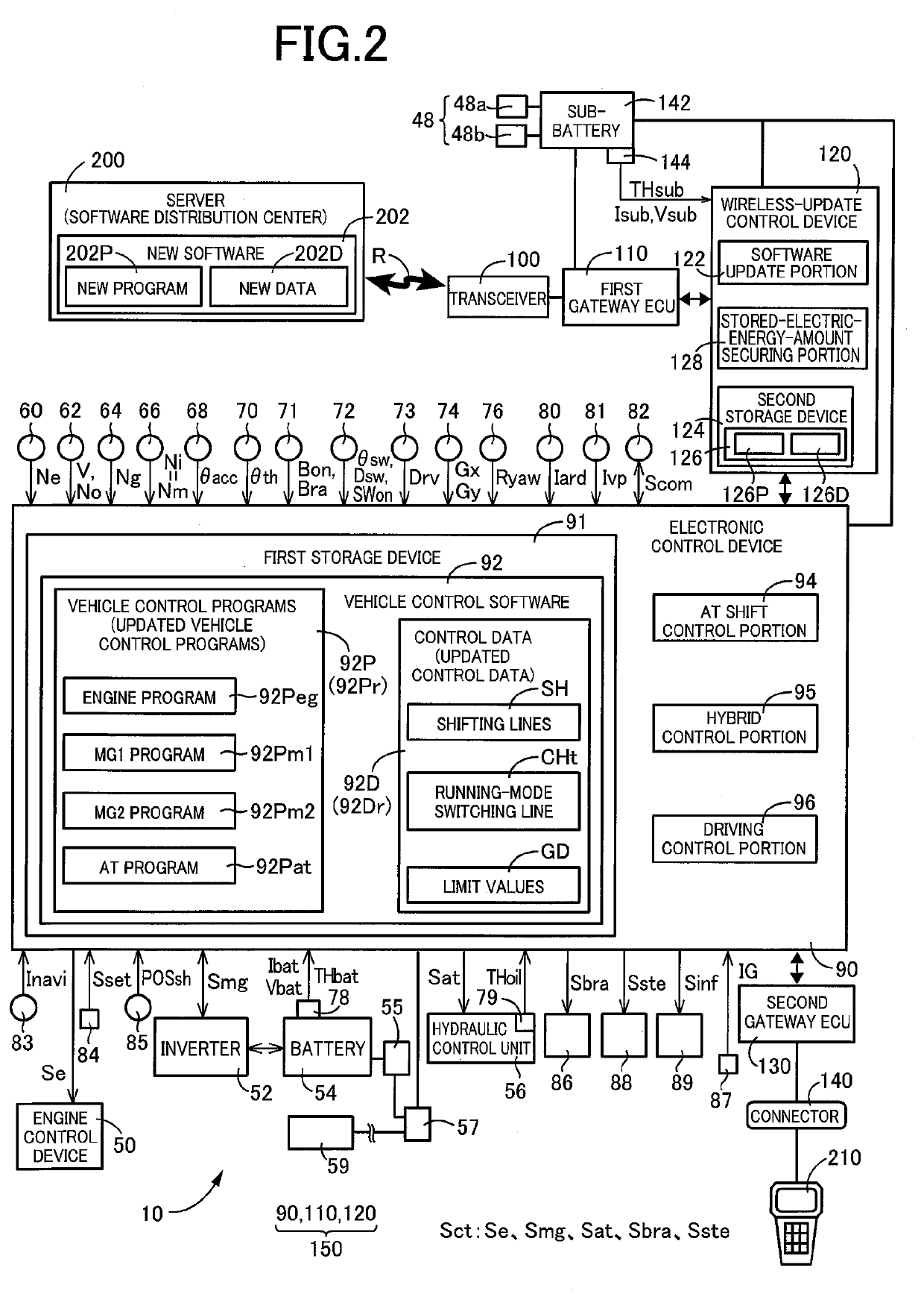
[0022]FIG. 1 is a view schematically showing a construction of a vehicle 8 to which the present invention is applied. FIG. 2 is a view schematically showing a construction of an in-vehicle system 10 for executing various control operations in the vehicle 8 of FIG. 1. As shown in FIG. 1, the vehicle 8 includes a power transmission apparatus 12, an engine 14 and first and second rotating machines MG1, MG2.

[0023]The in-vehicle system 10 shown in FIG. 2 is provided in the vehicle 8, so as to execute the various control operations in the vehicle 8. As shown in FIG. 2, the in-vehicle system 10 includes an electronic control device 90, a first gateway ECU 110, a wireless-update control device 120, a second gateway ECU 130, a high-voltage battery 54 configured to supply an electric power to the first and second rotating machines MG1, MG2, an auxiliary-device battery 57 configured to supply the electric power to devices provided in the vehicle 8, and a sub-battery 142.

[0024]The engine 14 is ...


PUM


Abstract

An in-vehicle system that is to be provided in a vehicle. The in-vehicle system includes: (a) a control apparatus; (b) a first battery configured to supply an electric power to devices that are to be provided in the vehicle; and (c) a second battery provided apart from the first battery. The in-vehicle system is constructed such that rewriting of a software of the control apparatus is executable when an electric power switch of the vehicle is in an OFF state, and such that the rewriting of the software is executed with supply of the electric power from the second battery to the control apparatus when the electric power switch of the vehicle is in the OFF state.

Description

[0001]This application claims priority from Japanese Patent Application No. 2020-142143 filed on Aug. 25, 2020, the disclosure of which is herein incorporated by reference in its entirety.FIELD OF THE INVENTION[0002]The present invention relates to an in-vehicle system that is to be provided in a vehicle, wherein the in-vehicle system includes a control apparatus capable of rewriting a software.BACKGROUND OF THE INVENTION[0003]There is known an in-vehicle system including an electronic control device (ECU) capable of rewriting a software. An example of such an in-vehicle system is disclosed in JP2019-64424A. This Japanese Patent Application Publication discloses that rewriting of the software of the electronic control device (ECU) is made with use of an electric power supplied from an auxiliary-device battery.SUMMARY OF THE INVENTION[0004]By the way, it is possible to easily secure a time required for rewriting the software of the electronic control device (ECU) when an electric pow...

Claims


Application Information

Patent Timeline
Patent Type & Authority Applications(United States)
IPC IPC(8): B60W20/13B60L58/13G06F8/65B60W20/20
CPCB60W20/13B60W20/20G06F8/65B60L58/13B60R16/033B60K6/445B60L2270/40B60L50/60B60L58/20B60L50/16B60L2240/50B60L2240/48B60L1/003B60L2240/443B60L2240/423B60L2250/26B60L2240/622Y02T10/62Y02T10/64Y02T10/70Y02T10/72Y02T10/7072Y02T90/16
Inventor TABATA, ATSUSHIOKUDA, KOICHIYAMAMOTO, MASAFUMIMAKINO, YUUKISUZUKI, SHOTARO
Owner TOYOTA JIDOSHA KK
Why Eureka
Try Eureka