Method for illuminating space

a space and light source technology, applied in the field of space illumination, can solve the problems of reducing energy, comparatively short life of fluorescent light as light source, and reducing the efficiency of light source, so as to increase the horizontal illuminance, increase the efficiency of illumination, and reduce electric energy

Inactive Publication Date: 2014-10-09
GIGATERA INC
View PDF1 Cites 2 Cited by
  • Summary
  • Abstract
  • Description
  • Claims
  • Application Information

AI Technical Summary

Benefits of technology

[0024]A method for illuminating a space of the present invention may properly control a distribution ratio between a horizontal illuminance and a vertical illuminance, that is, the method may distribute the horizontal illuminance and the vertical illuminance according to a use of an interior space, and thus there is an effect of decreasing electric energy by increasing an efficiency of an illumination.
[0025]In addition, the present invention may properly control a distribution ratio between a horizontal illuminance and a vertical illuminance, for example, may increase the horizontal illuminance more than the vertical illuminance in a case of an interior space such as a normal office or a library and may increase the vertical illuminance more than the horizontal illuminance in a case of a hallway of a hotel or a goods display space in a side of a market and so on to properly control distribution ratio according to a use of a corresponding space, and thus there is an effect of improving a concentration due to an illumination.

Problems solved by technology

The fluorescent light as a light source is comparatively cheap, but a life time thereof is comparatively short, and the longer a period of use is, the lower a brightness thereof is.
However, the above-mentioned conventional method for illuminating a space cannot obtain an effect of decreasing energy largely, although the conventional method for illuminating a space uses the LED of which efficiency is high.

Method used


Image

  • Method for illuminating space
  • Method for illuminating space
  • Method for illuminating space

Examples


Embodiment Construction

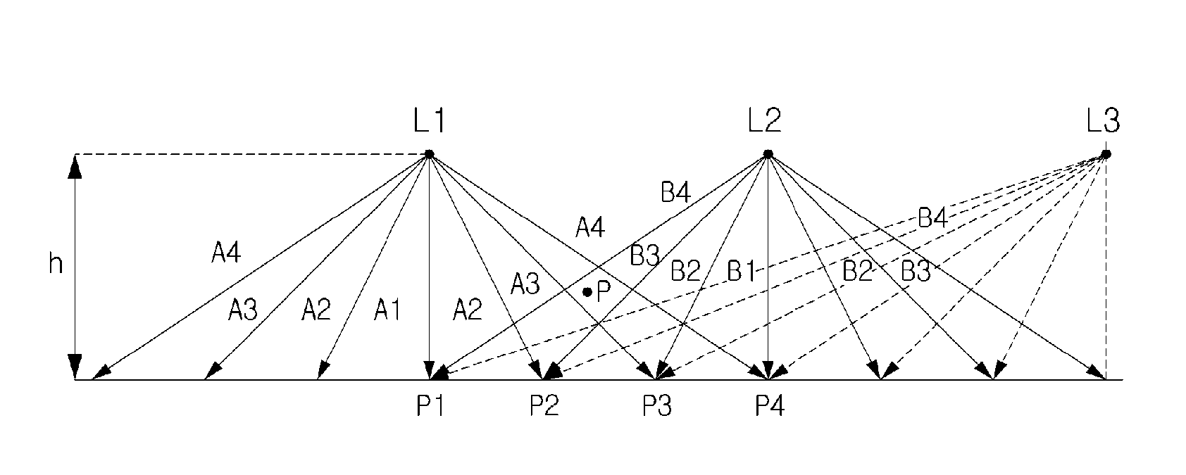
[0033]Hereinafter, a method for illuminating a space according to a preferable exemplary embodiment of the present invention is described in detail with reference to accompanying drawings.

[0034]In the present exemplary embodiment, as a method for illuminating a space, controlling a ratio between a whole of a horizontal illuminance and a vertical illuminance within a space, by controlling a light distribution condition of an LED illuminating module, in a space where a plurality of LED illuminating modules are disposed, is described.

[0035]Hereinafter, first, limiting a radiation angle of each of illuminating modules is described.

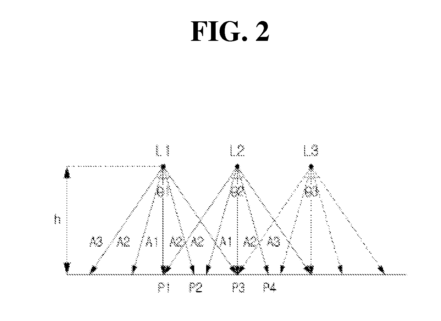
[0036]FIG. 2 is a description view for describing the method for illuminating a space according to a preferable exemplary embodiment of the present invention. In FIG. 2, it is described that a vertical illuminance decreases and a horizontal illuminance increases within the space, as an example.

[0037]Referring to FIG. 2, the method for illuminating a space acco...


PUM


Abstract

The present invention relates to a method for illuminating a space, and more specifically, to a method for illuminating a space using a plurality of LED illumination modules, wherein the plurality of LED illumination modules adjust a mutual distribution ratio between a vertical illuminance and a horizontal illuminance, which is greater than the vertical illumination, according to a limitation of a radiation angle at one point within the space having the constant volume. The present invention can increase the efficiency of illumination and can reduce electric energy by lowering the vertical illuminance compared to the horizontal illuminance.

Description

CROSS-REFERENCE TO RELATED APPLICATIONS[0001]This is a continuation of International Application No. PCT / KR2012 / 011292 filed on Dec. 21, 2012, which claims priority to Korean Application No. 10-2011-0141544 filed on Dec. 23, 2011, which applications are incorporated herein by reference.TECHNICAL FIELD[0002]The present invention relates to a method for illuminating a space, and more particularly, to a method for illuminating a space capable of increasing energy efficiency when an interior space such as an office and so on is illuminated.BACKGROUND ART[0003]Generally, an illumination of an interior space such as an office and so on uses a plurality of fluorescent lights installed on a ceiling. The fluorescent light as a light source is comparatively cheap, but a life time thereof is comparatively short, and the longer a period of use is, the lower a brightness thereof is.[0004]In addition, a radiation angle, which is a radiated angle of a light, of the fluorescent light is equal to or...

Claims


Application Information

Patent Timeline
Patent Type & Authority Applications(United States)
IPC IPC(8): F21K99/00F21V7/00
CPCF21V7/00F21K9/10F21K9/00F21S2/00F21V7/0058F21Y2105/10F21Y2115/10H05B45/10H05B47/10F21S2/005F21V7/0066F21K9/20F21K9/68H05B45/00H05B33/00
Inventor KIM, DUK YONG
Owner GIGATERA INC
Why Eureka
Try Eureka