Magnetic field characterization of stresses and properties in materials

a magnetic field and stress technology, applied in the direction of magnetic property measurement, material magnetic variables, instruments, etc., can solve the problems of catastrophic failure of the component, serious deformation of the mechanical properties of the ultra-high strength steel, and compromising the integrity of the componen

Active Publication Date: 2010-02-25
JENTEK SENSORS
View PDF1 Cites 16 Cited by
  • Summary
  • Abstract
  • Description
  • Claims
  • Application Information

AI Technical Summary

Benefits of technology

[0009]Aspects of the embodiment of the invention described herein involve novel sensors and sensor arrays for the measurement of the near surface properties of conducting and / or magnetic materials. These sensors and arrays use novel geometries for the primary winding and sensing elements that promote accurate modeling of the response and provide enhanced observability of property changes of the test material.
[0010]Methods are described herein for the monitoring of material properties as they are changed during processing. This can involve disposing an eddy current sensor or sensor array in proximity to the test material and converting the response of each sensor or sense element into an effective material property. In one embodiment, the sense elements are sensing coils the respond to absolute changes in the magnetic field response. Preferably, these coils are rectangular. In another embodiment, the sense elements incorporate GMR sensors. In a preferred embodiment, the leads to the sense elements also have a proximate set of leads that permit cancellation of the stray magnetic flux to the leads and permits the use of small sense elements. In one embodiment of the invention, the process being monitored is the heat treatment of a material. In one embodiment, the effective property is the electrical conductivity. In another, it is the lift-off. In one embodiment, the measurements are performed at multiple excitation frequencies. In another embodiment, the sensor is not in contact with the surface of the test material, which helps to minimize any effects the monitoring system may have on the environment around the material being processed.
[0015]Also described are methods for monitoring of the state of a material or a test article. In one embodiment, a sensor is placed in proximity to a test material to measure an electrical property of the state of the article. In one embodiment, the electrical property is the magnetic permeability and in another the electrical property is the electrical conductivity. In one embodiment, the state is stress and in another it is temperature. In another embodiment the state is an overload condition. Preferably, this overload condition results from excessive temperature expose as a thermal overload or from over stressing as a mechanical overload. Alternatively, the state can reflect the accumulation of fatigue damage of the presence of a crack within the test article. In another embodiment, the state of the article may be inferred from state-sensitive material layers. These layers may be placed on the surface of the article or embedded within layers of the article. In one embodiment, the state-sensitive material can be split into strips or some other geometry that facilitates a rapid inspection or indication of state changes. Preferably, the strips have different orientations with depth into the test article so that the depth of the state change can also be readily determined. In a further embodiment, these methods are used to remotely monitor the state or properties of a hidden material so that other material layers are present between the sensor and the material layer of interest.
[0016]In one embodiment for monitoring the properties of the materials, the sensors can be eddy current sensors. In one embodiment, the sensors have separate layers for the drive winding and sense elements. In another embodiment, the conductors for the drive and sense elements are placed in different layers on the test article itself. In another embodiment, the sensor is an array of eddy current sensors. These sensors can be mounted to the surface of the material or scanned over the surface of the article. In another embodiment, the sensor is a dielectric sensor. In another, it is a GMR sensor. These sensors can also be protected from environmental damage by durable layers. Suitable durable materials depend upon the type of sensor and the environment. In one embodiment, the durable medium is a ceramic. In another, it is a stainless steel.

Problems solved by technology

However, unintentional loading of these components, such as a hard landing, can impart residual stresses that compromise the integrity of the component.
Similarly, the mechanical properties of these ultra-high strength steels can be seriously degraded as a result of the ingress of hydrogen.
The resulting hydrogen embrittlement is unpredictable and can cause catastrophic failure of the component.
Hydrogen embrittlement has been established as the direct cause of numerous landing gear failures.
Management of high-strength steel components embrittled by hydrogen is made more difficult by the fact that failures are typically delayed, occurring some time after ingress of atomic hydrogen.
Cracks at these critical locations often initiate close to but beneath the surface, making them more difficult to detect.
This review also indicated that practical and cost-effective methods for assessment of residual stresses as well as for monitoring of applied stresses over wide areas in steel components are not yet available.
However this requires intimate fixed contact between the strain gage and the MUT and individual connections to each of the strain gages, both of which limit the potential usefulness for monitoring stress over large areas.
Furthermore, strain gages are limited in durability and do not always provide sufficient warning of gage failure or malfunction.
However, attempts to use conventional inductive, i.e., eddy-current sensors for assessment of residual stresses as well as for a number of other applications have shown serious limitations, particularly for complex geometry components.
Conventional eddy-current sensors widely used in nondestructive testing applications are effective at examining near surface properties of materials, but have a limited capability to examine material property variations deep within a material.
In contrast, ultrasonic techniques that are also widely used are effective at measuring property variations deep within a material, but have limited sensitivity near the surface and behind some geometric features such as air gaps.

Method used


Image

  • Magnetic field characterization of stresses and properties in materials
  • Magnetic field characterization of stresses and properties in materials
  • Magnetic field characterization of stresses and properties in materials

Examples


Embodiment Construction

[0053]A description of preferred embodiments of the invention follows.

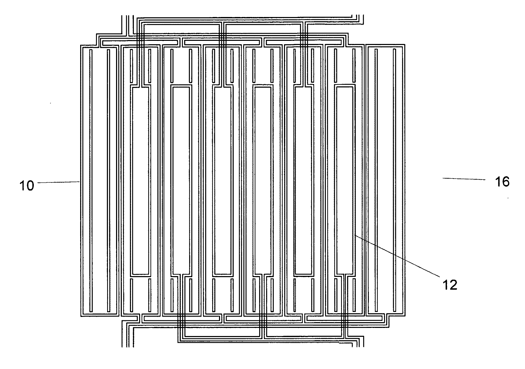
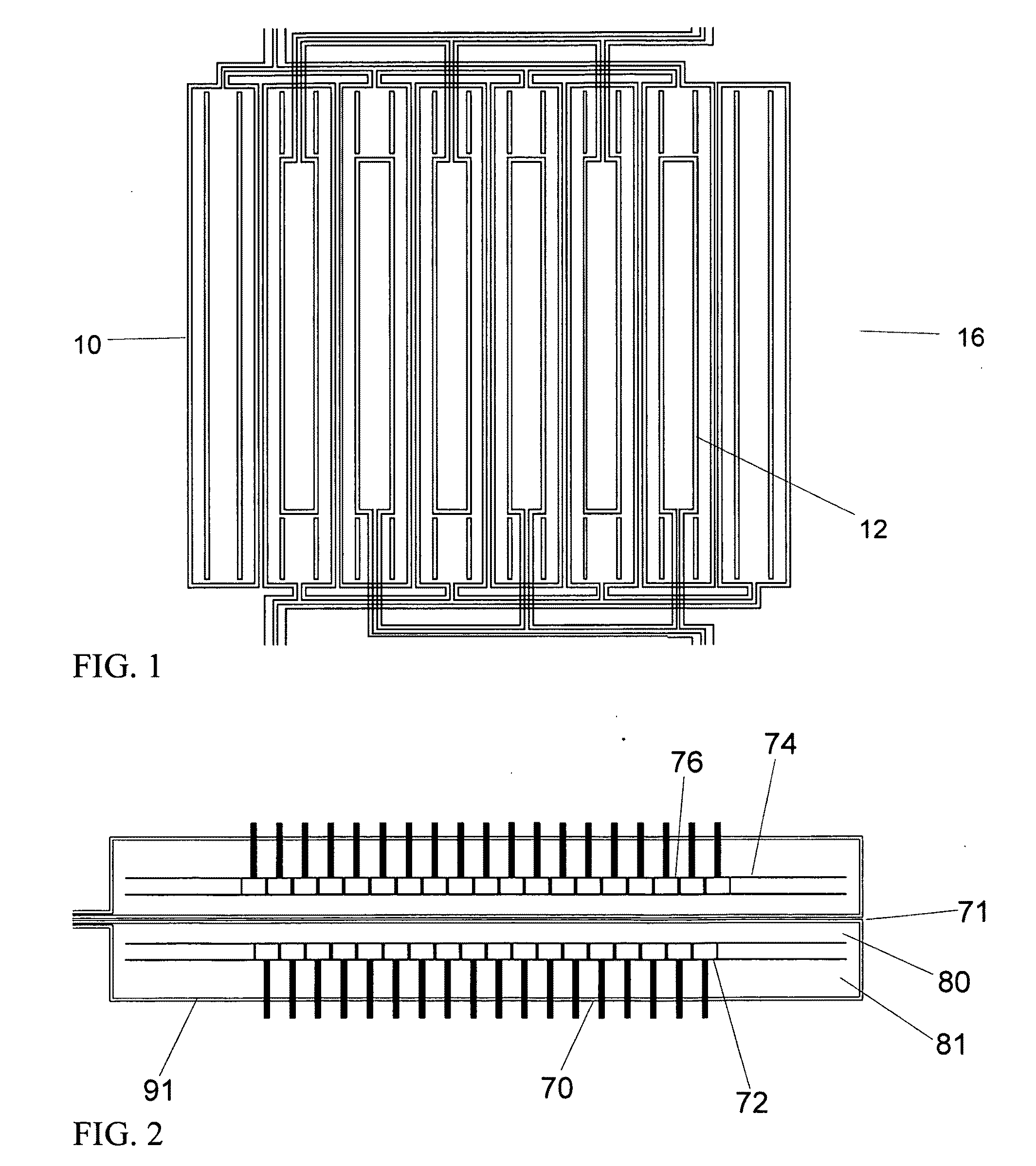
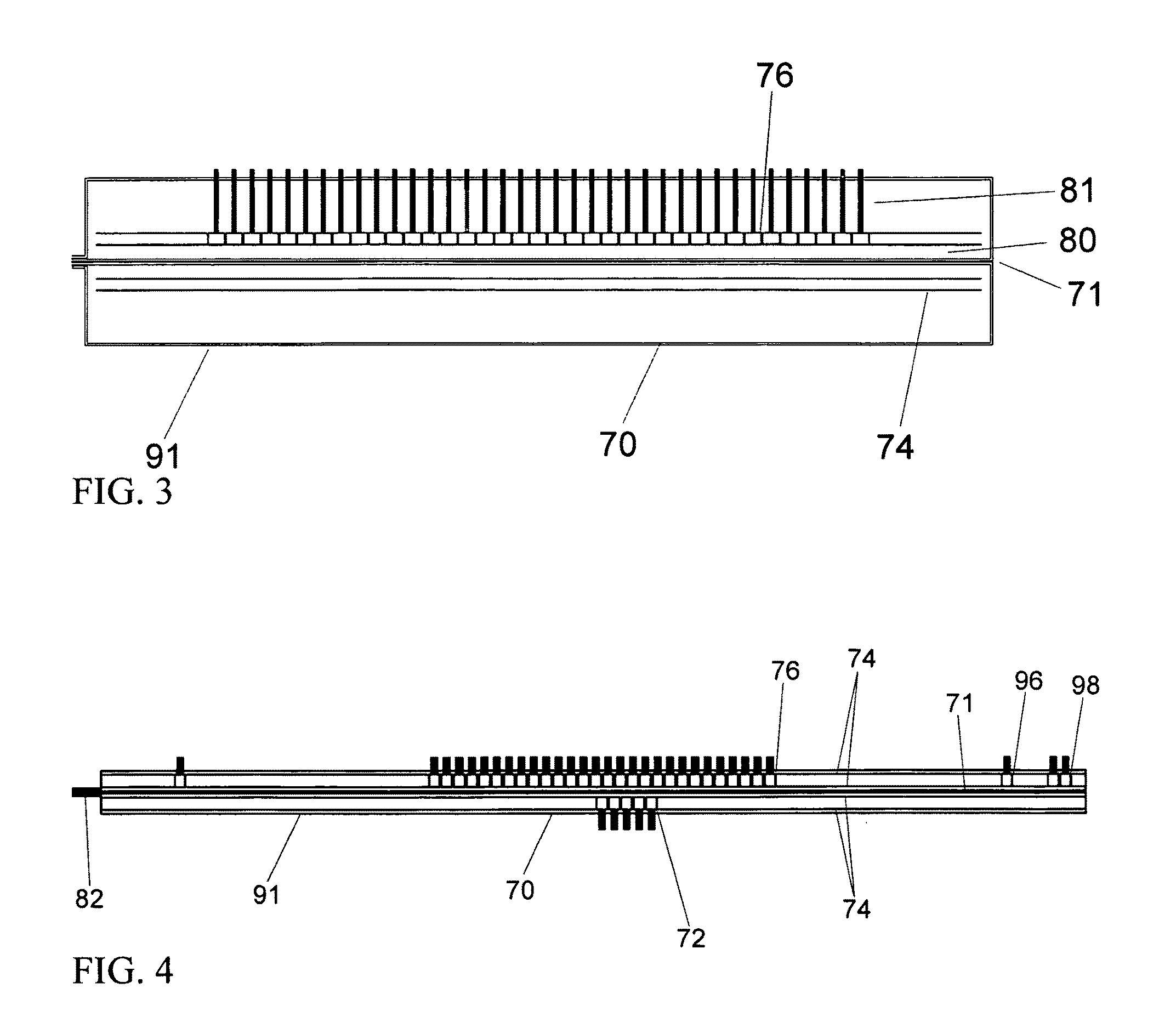
[0054]The use of conformable and nonconformable eddy-current sensors and sensor arrays is described herein for the nondestructive characterization of materials, particularly as it applies to the characterization of applied and residual stresses. This includes surface mounted and scanning, contact and non contact configuration. This sensing approach can be used to monitor the material characteristics at a given location with single or multiple sensing element sensors, sensor arrays and / or networks of surface mounted sensors using hand-held probes, mounted into automated scanners or as part of an embedded network. The sensors can be mounted into a structure in proximity to a material under test for monitoring the property changes while the material is being stressed and fatigued. Alternatively, such embedded sensors can be queried with instrumentation on a scheduled or unscheduled basis with either no electronics on...


PUM

PropertyMeasurementUnit
thickaaaaaaaaaa
temperaturesaaaaaaaaaa
frequencyaaaaaaaaaa

Abstract

Described are methods for monitoring of stresses and other material properties. These methods use measurements of effective electrical properties, such as magnetic permeability and electrical conductivity, to infer the state of the test material, such as the stress, temperature, or overload condition. The sensors, which can be single element sensors or sensor arrays, can be used to periodically inspect selected locations, mounted to the test material, or scanned over the test material to generate two-dimensional images of the material properties. Magnetic field or eddy current based inductive and giant magnetoresistive sensors may be used on magnetizable and / or conducting materials, while capacitive sensors can be used for dielectric materials. Methods are also described for the use of state-sensitive layers to determine the state of materials of interest. These methods allow the weight of articles, such as aircraft, to be determined.

Description

RELATED APPLICATIONS[0001]This application is a divisional of U.S. application Ser. No. 11 / 292,146, filed Nov. 30, 2005, which is a divisional of U.S. application Ser. No. 10 / 441,976, filed May 20, 2003, which claims the benefit of U.S. Provisional Application No. 60 / 382,447, filed May 21, 2002,U.S. Provisional Application No. 60 / 384,006, filed May 28, 2002, and U.S. Provisional Application No. 60 / 388,103, filed Jun. 11, 2002.[0002]The entire teachings of the above applications are incorporated herein by reference.GOVERNMENT SUPPORT[0003]The invention was supported, in whole or in part, by a grant F09650-01-M-0956 from the U.S. Air Force. The Government has certain rights in the invention.BACKGROUND OF THE INVENTION[0004]The technical field of this application is that of nondestructive materials characterization, particularly quantitative, model-based characterization of surface, near-surface, and bulk material condition for flat and curved parts or components using magnetic field b...

Claims


Application Information

Patent Timeline
Patent Type & Authority Applications(United States)
IPC IPC(8): G01R33/18G01N27/90
CPCG01N27/9013
Inventor GOLDFINE, NEIL J.SHAY, IAN C.SCHLICKER, DARRELL E.WASHABAUGH, ANDREW P.GRUNDY, DAVID C.LYONS, ROBERT J.ZILBERSTEIN, VLADIMIR A.TSUKERNIK, VLADIMIR
Owner JENTEK SENSORS
Why Eureka
Try Eureka