
Hybrid wound/etched winding constructs for scanning and monitoring

a technology of etching and winding, applied in the direction of magnetic measurement, instruments, measurement devices, etc., can solve the problems of excessively long scanning time and care, and achieve the effect of enhancing the observability of property changes and promoting accurate modeling of responses

Active Publication Date: 2009-04-14
JENTEK SENSORS
View PDF56 Cites 11 Cited by
  • Summary
  • Abstract
  • Description
  • Claims
  • Application Information

AI Technical Summary

Benefits of technology

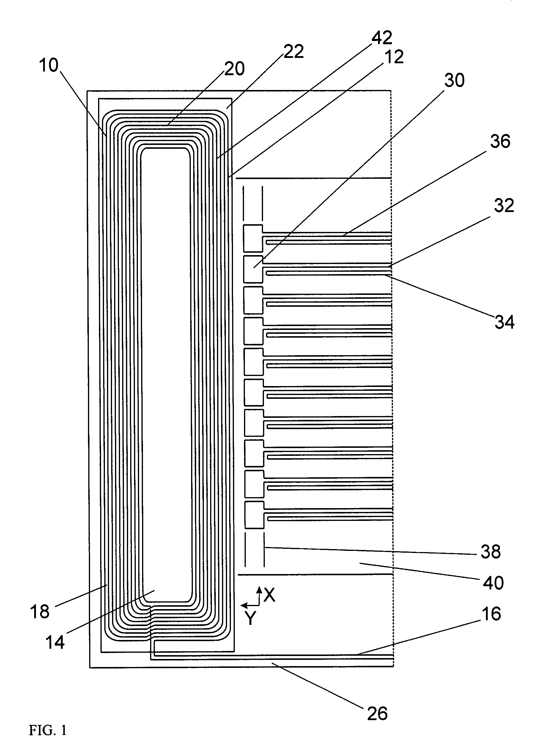
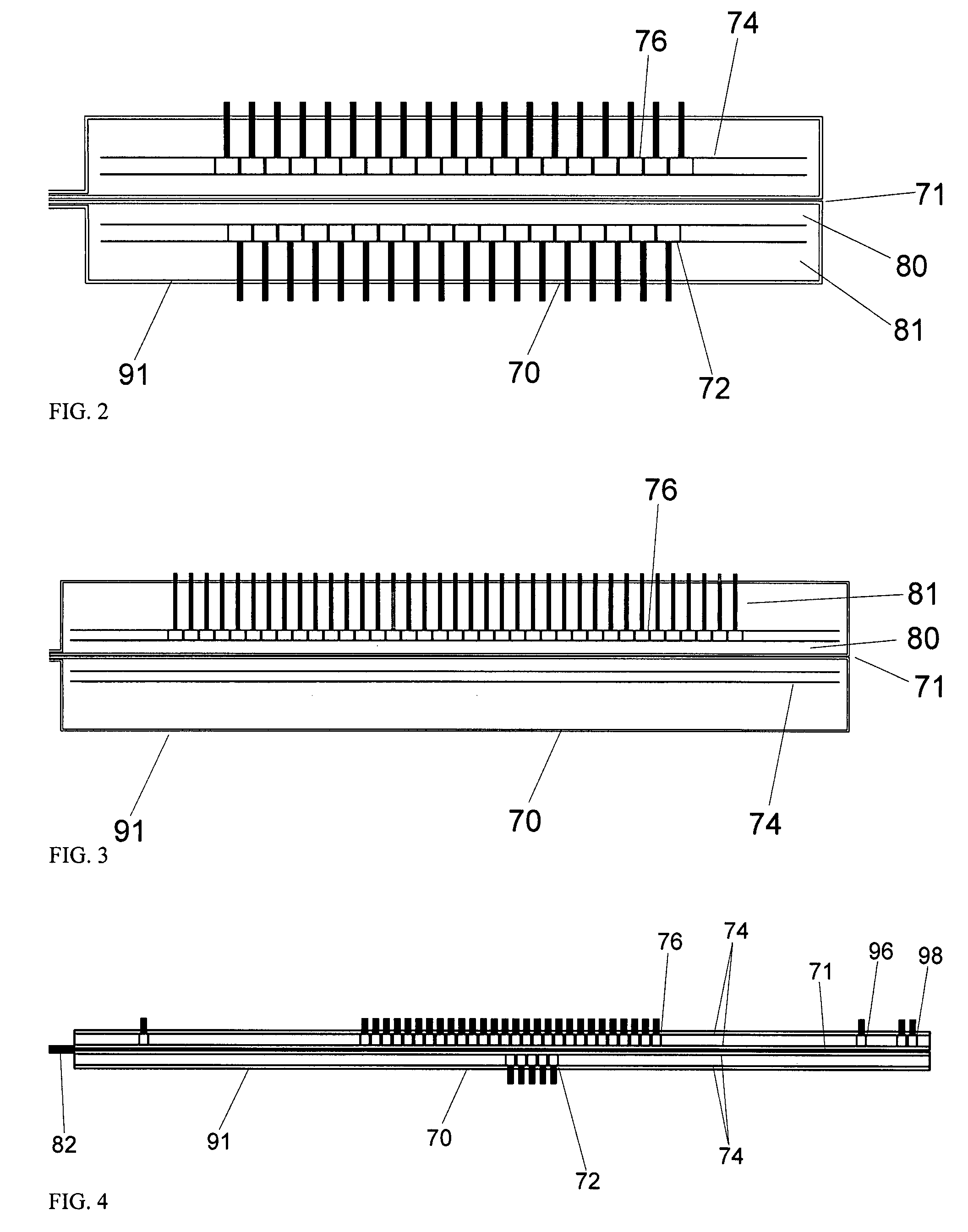
[0006]Aspects of the methods described herein involve novel sensors and sensor arrays for the measurement of the near surface properties of conducting and / or magnetic materials. These sensors and arrays use novel geometries for the primary winding and sensing elements that promote accurate modeling of the response and provide enhanced observability of property changes of the test material.
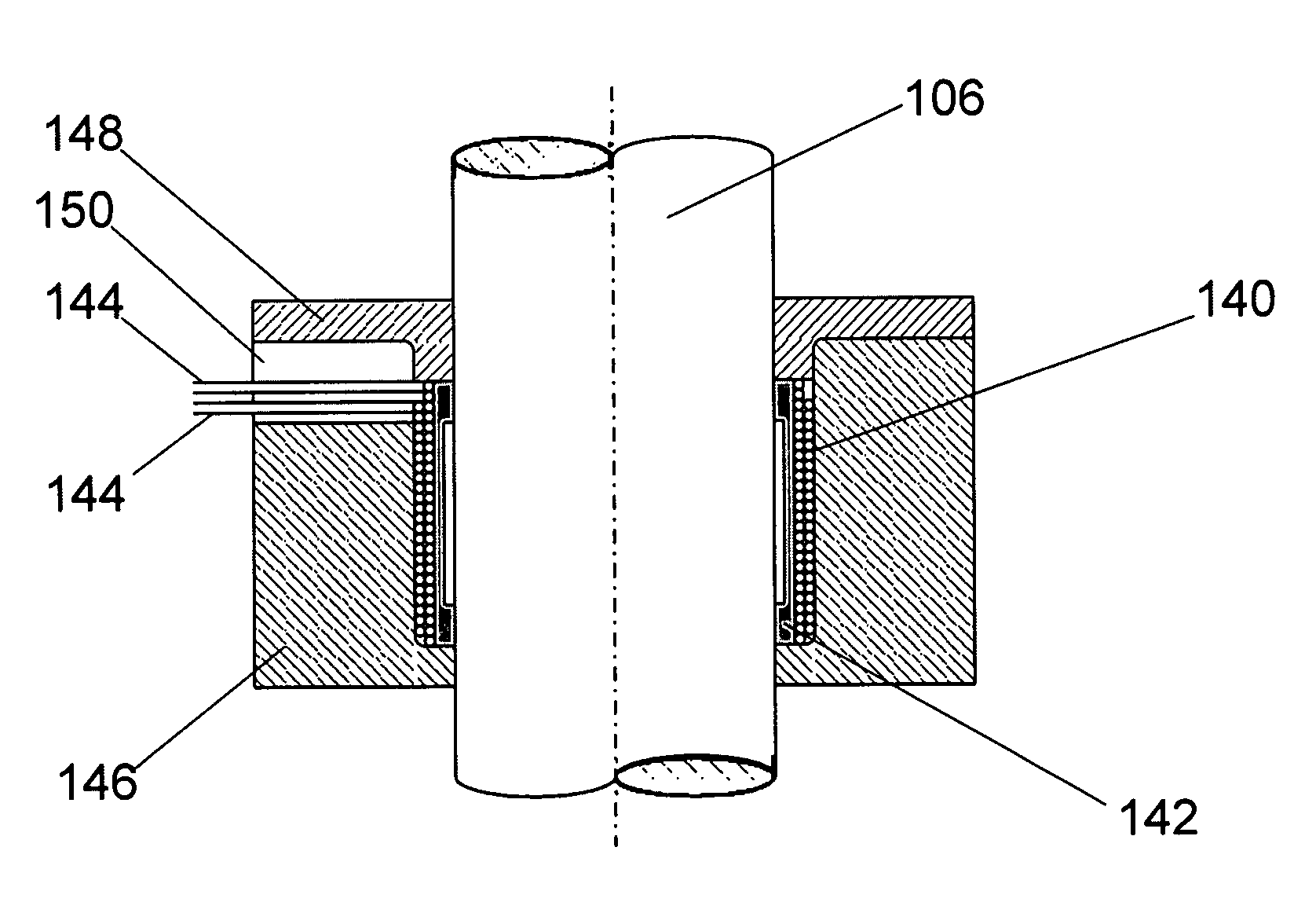
[0010]In an embodiment, the drive winding coil is located around a feature associated with the material under test, such as a fastener or a bolt. The drive is placed near the test material surface and can be placed around the fastener head or nut or between the test material surface and the fastener head or nut. The fabricated array of sense elements, which can be inductive, are then positioned or scanned around the fastener or positioned between other material layers or even on an opposing surface of the test material in the same region as the drive coil. The sense elements can be fabricated using etched or printed circuit manufacturing techniques, can be oriented to be sensitive to different components of the magnetic field, and in another embodiment, are located at varied radial distances from the drive coil. The substrate for the sense elements may be flexible to provide conformability to the test material surface and measurements can be performed at different lift-offs or proximities to the test material surface. The locations of the drive coil and sense elements could also be reversed, with the sense elements mounted under the fastener and the drive coil scanned or positioned around the fastener. Again, these embodiments can provide the desired observability to a feature or material property of interest, such as a buried crack, stress at an interface or stress in a bolt.
[0011]To improve the penetration of the magnetic field into the test material, a variety of methods are employed. In an embodiment, the drive coil is embedded in a material that supports the mechanical load but does not cause significant attenuation of the magnetic field from the drive coil. This is accomplished by making the support material from a relatively low electrical conductivity material, such as a composite, or splitting or laminating the support material to interrupt the flow of induced eddy currents. Similarly, the fastener itself could be split or the nut could be from a relatively low conductivity material. Standoffs can also be used which increase the distance between the nut and the drive coil. Another embodiment uses magnetizable materials in the support material, such as ferrites, to guide the magnetic flux as in a magnetic circuit. The magnetizable material can be coated onto the shaft of the fastener or inside of hollow fasteners.

Problems solved by technology

However, use of a single sensor has disadvantages in that the scanning can take an excessively long time and care must be taken when registering the measured values together to form a map or image of the properties.

Method used


Image

  • Hybrid wound/etched winding constructs for scanning and monitoring
  • Hybrid wound/etched winding constructs for scanning and monitoring
  • Hybrid wound/etched winding constructs for scanning and monitoring

Examples


Embodiment Construction

[0040]A description of preferred embodiments of the invention follows.

[0041]The use of hybrid eddy-current sensors and sensor arrays is described herein for the nondestructive characterization of materials, particularly as it applies to the characterization of conducting and / or magnetic materials. This includes surface mounted and scanning, contact and non-contact configurations. This sensing approach can be used to monitor the material characteristics at a given location with single or multiple sensing element sensors, sensor arrays and / or networks of surface mounted sensors using hand-held probes, mounted into automated scanners or as part of an embedded network.

[0042]This invention describes the use of a combination of etched and wound winding constructs to construct an eddy current sensor or other inductive sensor, or a sensor with magnetic field measurement sensing element such as giant magnetoresistive (GMR) sensors, or with magnetic field (B field) and / or rate-of-field-change...


PUM

PropertyMeasurementUnit
corrosion lossaaaaaaaaaa

Abstract

Combined wound and micro-fabricated winding constructs are described for the inspection of materials and the detection and characterization of hidden features or flaws. These constructs can be configured as sensors or sensor arrays that are surface mounted or scanned over conducting and / or magnetizable test materials. The well-defined geometry obtained micro-fabricated windings and from carefully wound coils with known winding positions permits the use of model based inversions of sensed responses into material properties. In a preferred embodiment, the primary winding is a wound coil and the sense elements are etched or printed. The drive or sense windings can also be mounted under fasteners to improve sensitivity to hidden flaws. Ferrites and other means may be used to guide the magnetic flux and enhance the magnetic field in the test material.

Description

RELATED APPLICATIONS[0001]This application is a divisional of U.S. application Ser. No. 10 / 853,009, filed May 24, 2004, now abandoned which claims the benefit of U.S. Provisional Application No. 60 / 473,180 filed May 23, 2003 the entire teachings of which are incorporated herein by reference.BACKGROUND OF THE INVENTION[0002]This application relates to nondestructive materials characterization, particularly quantitative, model-based characterization of surface, near-surface, and bulk material condition for flat and curved parts or components using magnetic field based or eddy-current sensors. Characterization of bulk material condition typically includes (1) measurement of changes in material state, i.e., degradation / damage caused by fatigue damage, creep damage, thermal exposure, or plastic deformation; (2) assessment of residual stresses and applied loads; and (3) assessment of processing-related conditions, for example from aggressive grinding, shot peening, roll burnishing, therma...

Claims


Application Information

Patent Timeline
Patent Type & Authority Patents(United States)
IPC IPC(8): G01N27/82G01R33/12G01N27/90
CPCG01N27/82G01N27/9046
Inventor GOLDFINE, NEIL J.SCHLICKER, DARRELL E.WASHABAUGH, ANDREW P.SHAV, IAN C.WINDOLOSKI, MARK D.ROOT, CHRISTOPHERZILBERSTEIN, VLADIMIR A.GRUNDY, DAVID C.TSUKERNIK, VLADIMIR
Owner JENTEK SENSORS
Learn More