Imaging lens and imaging apparatus

a technology of imaging lens and imaging apparatus, which is applied in the direction of optics, instruments, optical elements, etc., can solve the problems of increased manufacturing costs, increased manufacturing costs, and low performance of imaging lenses, and achieves low manufacturing costs and small size. , the effect of low manufacturing cos

Active Publication Date: 2010-02-25
NANCHANG O FILM OPTICAL ELECTRONICS TECH CO LTD
View PDF4 Cites 36 Cited by
  • Summary
  • Abstract
  • Description
  • Claims
  • Application Information

AI Technical Summary

Benefits of technology

[0012]The invention has been made in order to solve the above-mentioned problems, and an object of the invention is to provide an imaging lens that has a small F number, a low manufacturing cost, and a small size and can obtain a high-quality image, and an imaging apparatus including the imaging lens.
[0014]As described above, according to the imaging lens of the first aspect, it is effective to obtain an optical system having a small size and a small F number by appropriately selecting the structure of each lens. Further, since the imaging lens does not necessarily use an aspheric surface, it is possible to reduce manufacturing costs. In addition, since the imaging lens according to the first aspect of the invention is configured so as to satisfy Conditional expression 1, it is effective to correct field curvature and prevent the generation of a ghost.
[0016]As described above, according to the imaging lens of the second aspect, it is effective to obtain an optical system having a small size and a small F number by appropriately selecting the structure of each lens. Further, since the imaging lens does not necessarily use an aspheric surface, it is possible to reduce manufacturing costs. In addition, in the imaging lens according to the second aspect of the invention, each of the lenses is a single lens. That is, the entire lens system does not use a cemented lens. Therefore, it is possible to manufacture an imaging lens with a low manufacturing cost.
[0022]According to the imaging lens of the first aspect of the invention, in a lens system including at least six lenses, for example, the shape and power of each lens is appropriately set to satisfy Conditional expression 1. Therefore, it is possible to achieve an imaging lens that has a small F number, a small size, and a low manufacturing cost and can obtain a high-quality image.
[0023]According to the imaging lens of the second aspect of the invention, in a lens system including at least six lenses, for example, the shape and power of each lens is appropriately set, and each of the lenses is a single lens. Therefore, it is possible to achieve an imaging lens that has a small F number, a small size, and a low manufacturing cost and can obtain a high-quality image.
[0024]According to the invention, the imaging apparatus includes the imaging lens according to the above-described invention. Therefore, it is possible to achieve an imaging apparatus that is suitable for an in-vehicle camera or a monitoring camera, has a small size and a low manufacturing cost, and can obtain a high-quality image.

Problems solved by technology

However, when the aspheric lens is made of resin, the performance of the imaging lens is likely to be lowered due to a temperature variation.
Therefore, when the imaging lens is used in a wide temperature range, problems may arise.
However, when the aspheric lens is made of glass, a glass mold is needed to manufacture the aspheric lens, which results in an increase in manufacturing costs.
However, since the imaging lens disclosed in Japanese Patent No. 3723637 has a large total length, sufficient reduction in the size of the imaging lens is not achieved.
Therefore, the imaging system is not fast enough to be used for an in-vehicle camera or a monitoring camera.
Therefore, there is a concern that it may be difficult to exactly recognize an image according to the degree of ghost.

Method used


Image

  • Imaging lens and imaging apparatus
  • Imaging lens and imaging apparatus
  • Imaging lens and imaging apparatus

Examples


Embodiment Construction

[0052]Hereinafter, exemplary embodiments of the invention will be described in detail with reference to the accompanying drawings. First, an imaging lens according to an embodiment of the invention will be described, and then an imaging apparatus according to another embodiment of the invention will be described.

[0053]An imaging lens according to the first embodiment of the invention, in a case where the stop is positioned in rear of the second lens will be described.

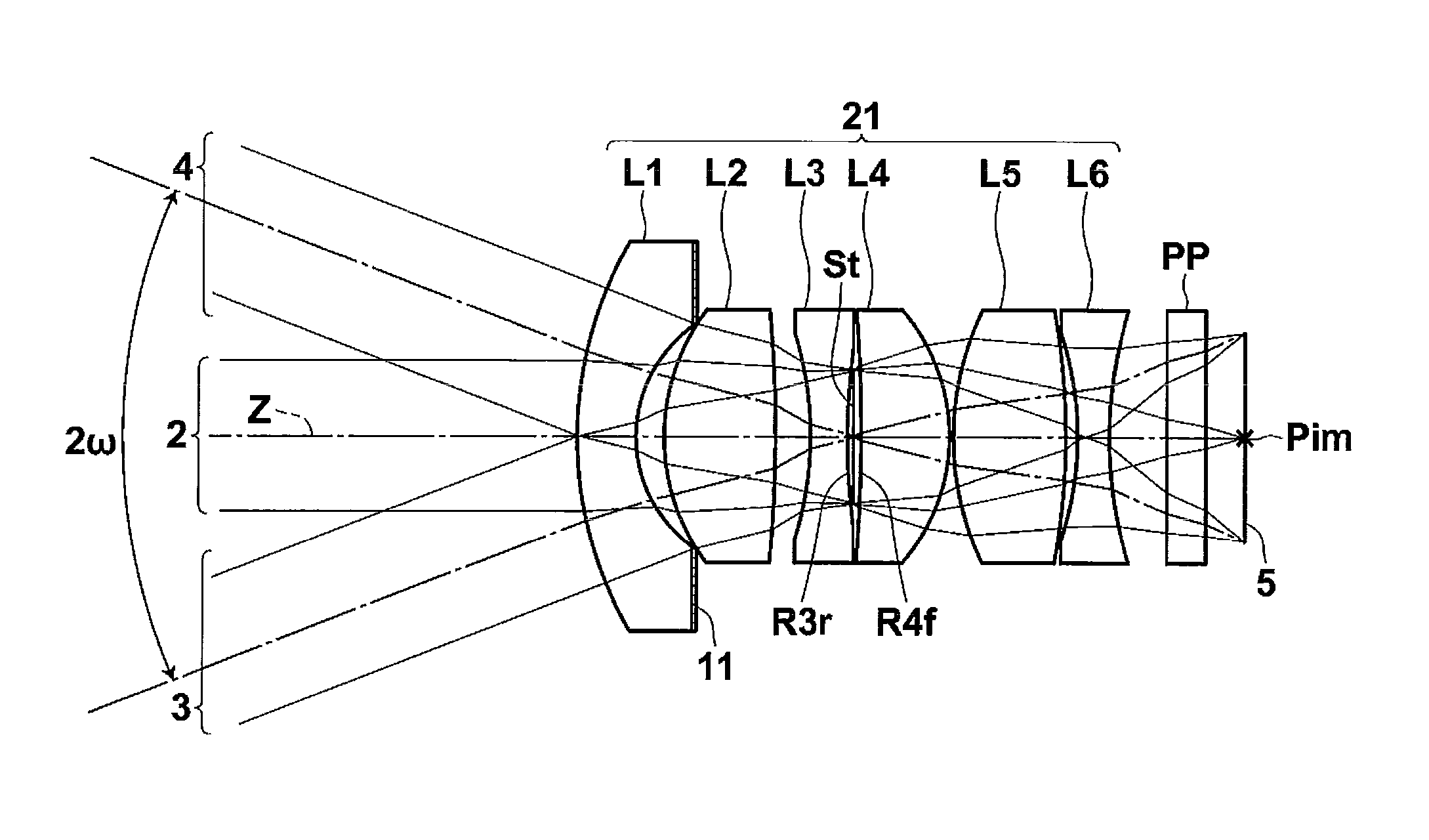
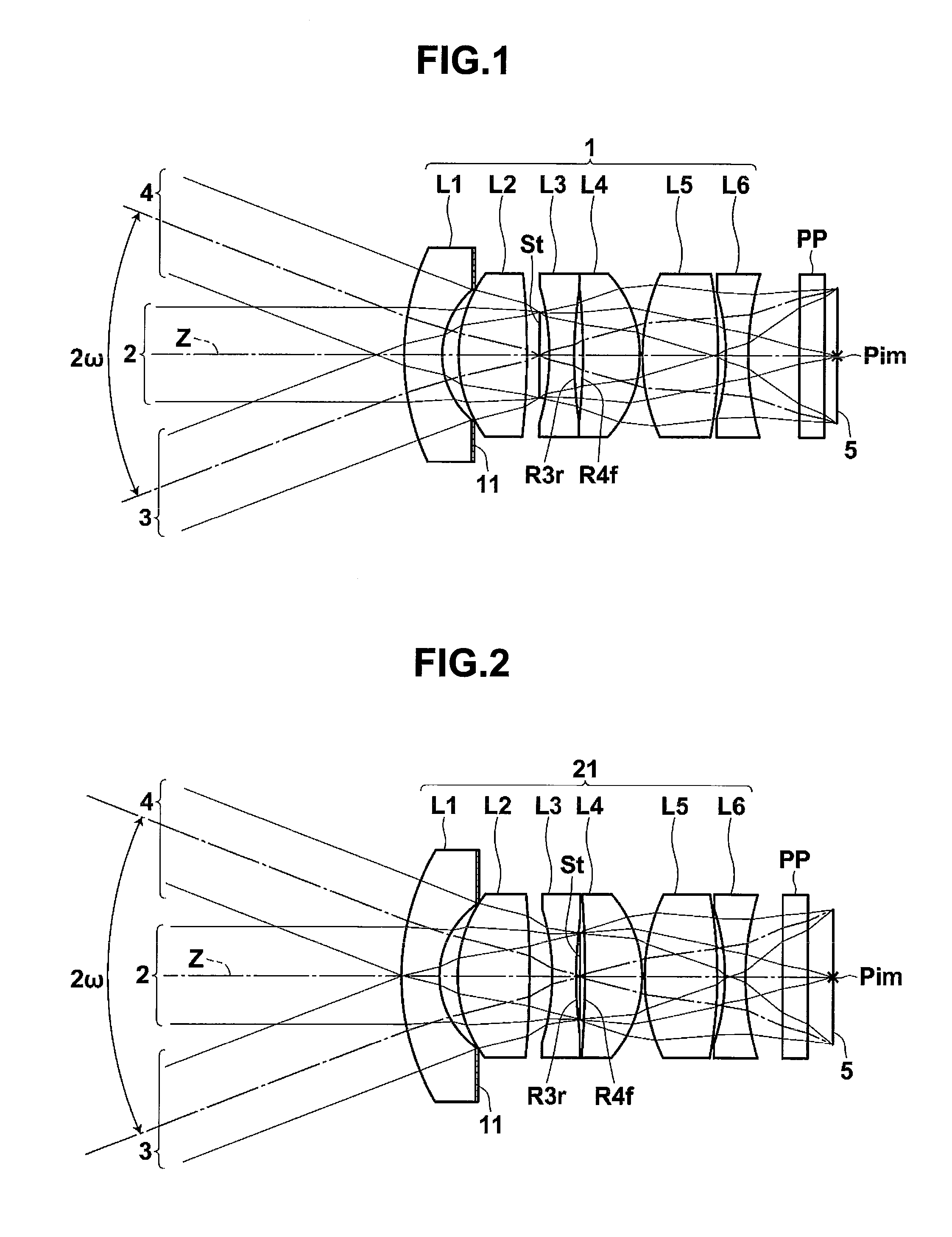
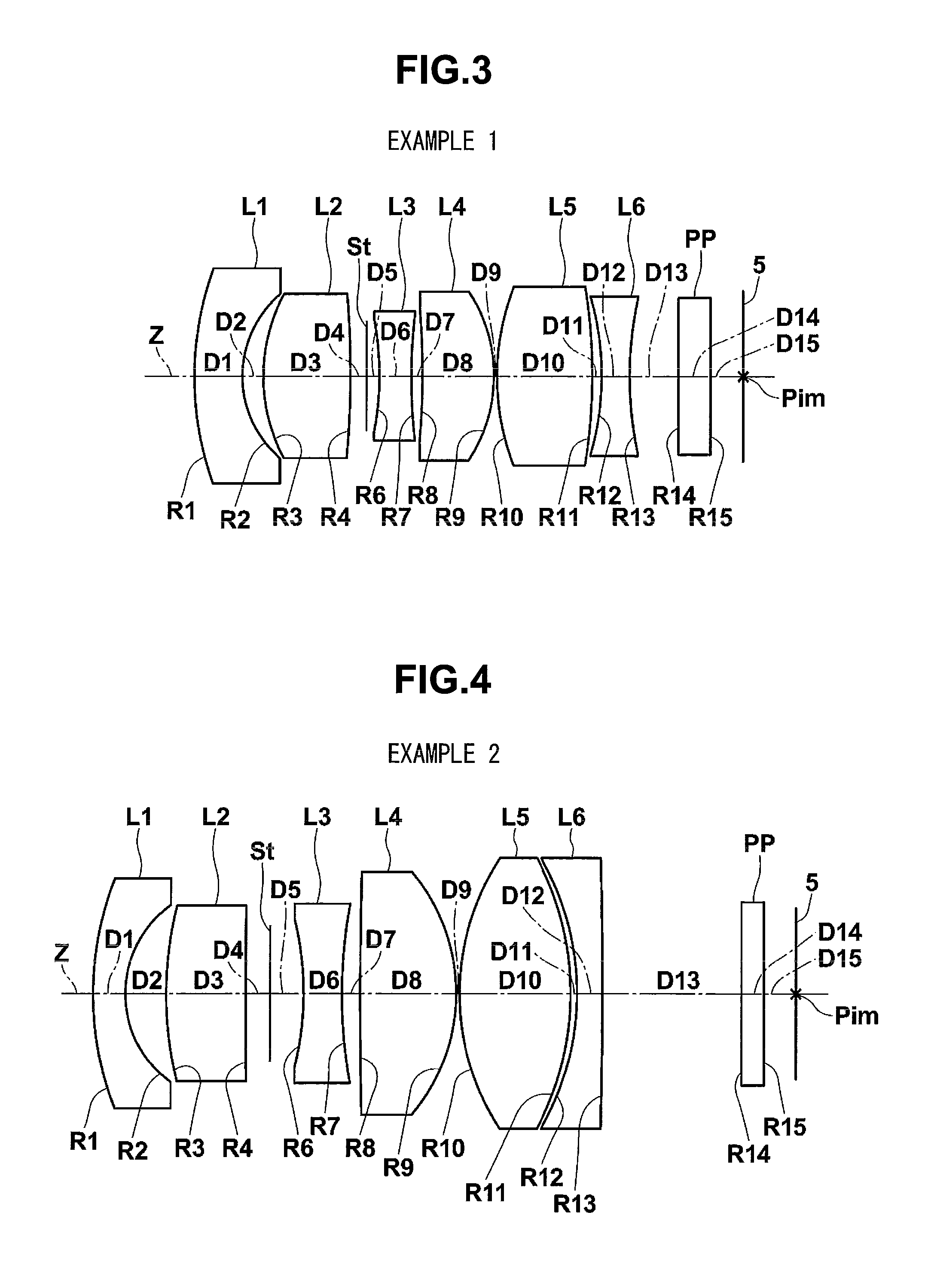
[0054]FIG. 1 is a cross-sectional view illustrating an imaging lens 1 according to a first embodiment of the invention. The structural example shown in FIG. 1 corresponds to the structure of a lens according to Example 1, which will be described below, shown in FIG. 3. In FIG. 1, the left side is an object side, and the right side is an image side. FIG. 1 also shows the focusing of an on-axis beam 2 from an infinite object point and off-axis beams 3 and 4 at a maximum angle of view. In this case, the on-axis beam is a b...


PUM


Abstract

Disclosed is an imaging lens having a small F number, a wide angle of view, and a low manufacturing cost and capable of obtaining a high-quality image.An imaging lens includes a first lens having a negative power and including a concave surface facing an image side, a second lens having a positive power, an aperture diaphragm, a third lens having a negative power, an aperture diaphragm, a fourth lens having a positive power, a fifth lens having a positive power and including a convex surface facing the image side, and a sixth lens having a negative power arranged in this order from an object side. When the curvature radius of an image-side surface of the third lens is R3r and the curvature radius of an object-side surface of the fourth lens is R4f, the imaging lens satisfies the following Conditional expression:|R3r / R4f|<1.0.

Description

CROSS-REFERENCE TO RELATED APPLICATIONS[0001]This application is based upon and claims the benefit of priority from the Japanese Patent Application No. 2008-212556 filed on Aug. 21, 2008; the entire contents of which are incorporated herein by reference.BACKGROUND OF THE INVENTION[0002]1. Field of the Invention[0003]The present invention relates to an imaging lens and an imaging apparatus, and more particularly, to an imaging lens applicable for, for example, an in-vehicle camera, a mobile terminal camera, or a monitoring camera using an imaging device, such as a CCD (charge coupled device) or a CMOS (complementary metal oxide semiconductor), and an imaging apparatus including the imaging lens.[0004]2. Description of the Related Art[0005]In recent years, the size of an imaging device, such as a CCD or a CMOS, has been reduced, and the number of pixels thereof has increased. In addition, the size of an imaging apparatus including the imaging device has been reduced. Therefore, it is ...

Claims


Application Information

Patent Timeline
Patent Type & Authority Applications(United States)
IPC IPC(8): G02B9/62
CPCG02B13/16G02B9/62
Inventor ASAMI, TARO
Owner NANCHANG O FILM OPTICAL ELECTRONICS TECH CO LTD
Why Eureka
Try Eureka