Light guide and light-output device

a technology of light guide and light output device, which is applied in the direction of lighting applications, lighting and heating apparatus, instruments, etc., can solve the problems of increasing the need to integrate lighting in interiors as unobtrusively as possible, and the requirement for in-coupled light to be highly collimated for proper function

Active Publication Date: 2010-02-25
SIGNIFY HLDG BV
View PDF14 Cites 141 Cited by
  • Summary
  • Abstract
  • Description
  • Claims
  • Application Information

AI Technical Summary

Benefits of technology

[0009]It is therefore an object of the present invention to mitigate at least some of the drawbacks of the prior art and to provide an improved light guide, enabling use of a wider variety of light-sources.

Problems solved by technology

To enable architects and interior designers to create interior styles that clearly distinguish one building from the other, however, there is an increasing need to integrate lighting in interiors as unobtrusively as possible.
A drawback of the light guide described in WO 2006 / 034831 is that it requires in-coupled light to be highly collimated to function properly.

Method used


Image

  • Light guide and light-output device
  • Light guide and light-output device
  • Light guide and light-output device

Examples


Embodiment Construction

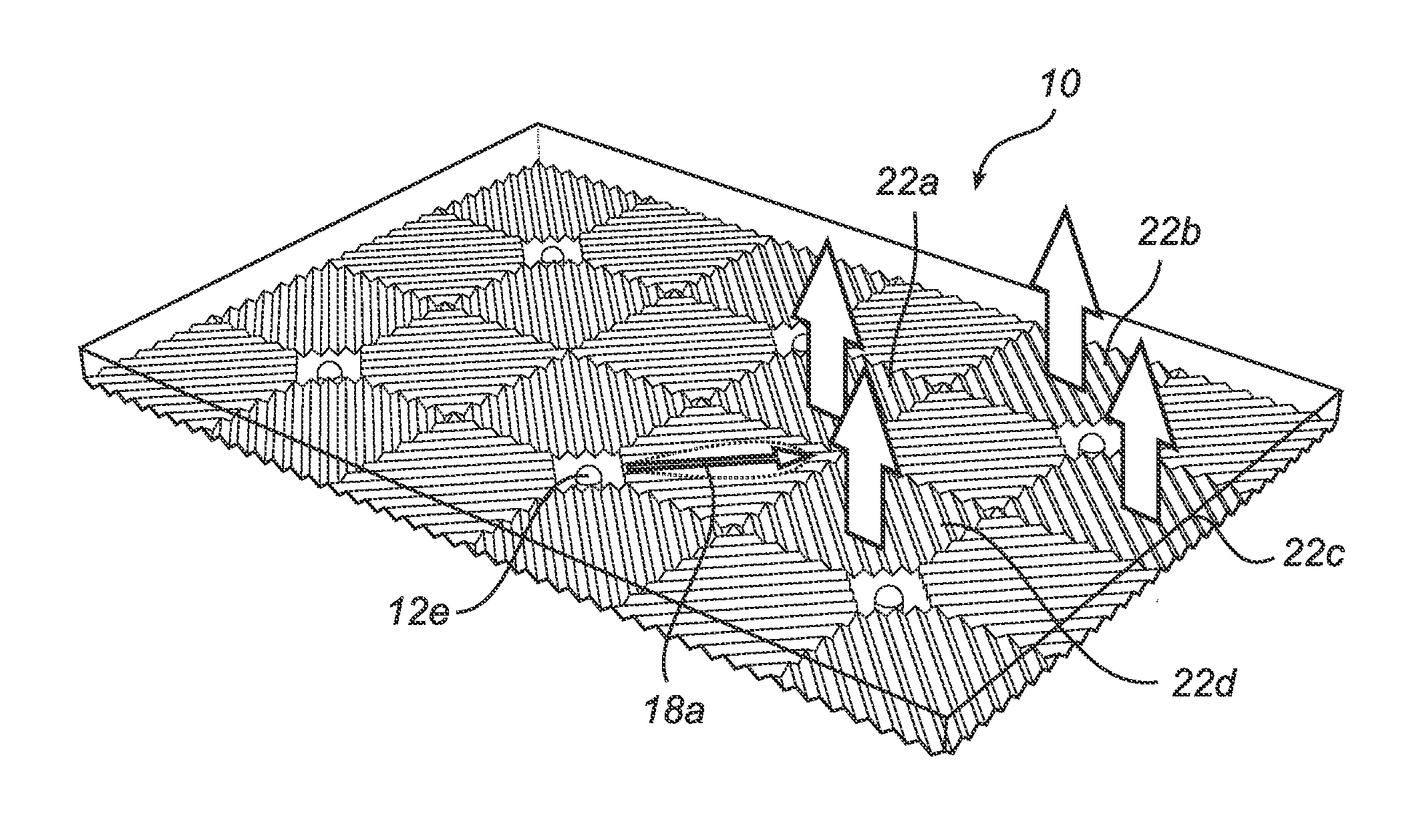
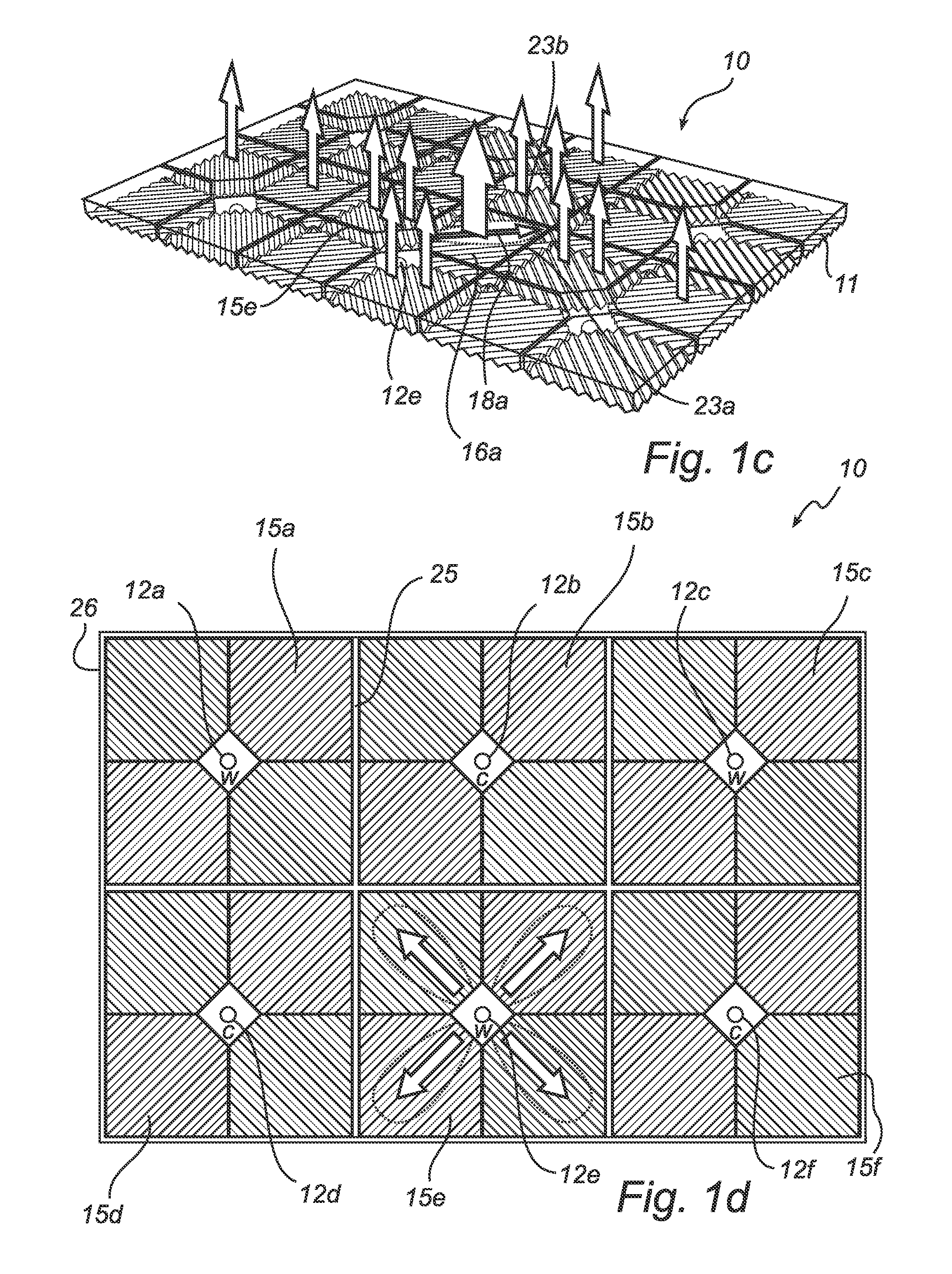
[0096]The present detailed description primarily relates to luminaires comprising a planar light-guide and one or several light-emitting diodes arranged in in-coupling recesses provided in one of the faces of the light-guide.

[0097]It should be noted that this by no means limits the scope of the invention, which is equally applicable to other types of light-sources, such as semiconductor lasers, and other kinds of in-coupling structures, including, for examples mirrors, prisms etc.

[0098]In the following, a number of preferred embodiments will be described.

[0099]First, with reference to FIGS. 1a-e, a basic configuration of a luminaire having a plurality of light-sources arranged in a square grid array will be described. In FIG. 1a an exemplary luminaire 10 is shown, comprising a light guide 11 and a plurality of light-sources 12a-f, here in the form of omni-directional LEDs, located at corresponding in-coupling portions 13a-f, which in FIG. 1a each are provided with an in-coupling str...


PUM


Abstract

A light guide (11; 101; 111) comprising first and second oppositely arranged faces, an in-coupling portion (13a-f) for in-coupling of light from a light-source (12a-f; 95a-f; 102; 106a-c; 112a-f), and an out-coupling portion (15a-f; 103; 113a-f) located adjacent to the in-coupling portion (13a-f). The out-coupling portion (15a-f; 103; 113a-f) is configured to out-couple a primary light beam having a direction of propagation directed from a position in the in-coupling portion (13a-f) with a lower out-coupling efficiency than a secondary light beam having a direction of propagation directed from a position in the light guide (11; 101; 111) outside the in-coupling portion (13a-f). In this manner, a good mixing of light in the light guide can be achieved without imposing any particular requirements on the collimation of the in-coupled light.

Description

TECHNICAL FIELD OF THE INVENTION[0001]The present invention relates to a planar light guide comprising first and second oppositely arranged faces, an in-coupling position for in-coupling of light from a light-source, and an out-coupling portion located adjacent to the in-coupling position.[0002]The present invention further relates to a light-output device including such a light guide and at least one light-source.TECHNICAL BACKGROUND[0003]As of today, fluorescent lighting is commonly used as the illumination system of choice for office lighting.[0004]To enable architects and interior designers to create interior styles that clearly distinguish one building from the other, however, there is an increasing need to integrate lighting in interiors as unobtrusively as possible.[0005]Conventional luminaires based on fluorescent lighting are known to have a minimum thickness of approximately 50 mm. Illumination systems based on alternative light-sources which allow for thin luminaries on t...

Claims


Application Information

Patent Timeline
Patent Type & Authority Applications(United States)
IPC IPC(8): F21V1/00F21S8/10F21V7/00
CPCF21W2131/40F21Y2101/02G02B5/045G02B6/0021G02B6/0073G02B6/0053G02B6/0055G02B6/0068G02B6/0036F21Y2115/10
Inventor PIJLMAN, FETZEIJZERMAN, WILLEM LUBERTUSCORNELISSEN, HUGO JOHANKRIJN, MARCELLINUS PETRUS CAROLUS MICHAELVAN GORKOM, RAMON PASCALWILLEMSEN, OSCAR HENDRIKUSVISSENBERG, MICHEL CORNELIS JOSEPHUS MARIE
Owner SIGNIFY HLDG BV
Why Eureka
Try Eureka