Receiving apparatus and mobile communication system

a technology of receiving apparatus and mobile communication system, which is applied in the direction of baseband system details, amplitude demodulation, line-faulst/interference reduction, etc., can solve the problems of inter-symbol interference (multipath interference), interference (other cell interference, other cell interference, etc.) and the effect of suppressing the interference of another cell

Active Publication Date: 2010-02-25
NEC CORP
View PDF2 Cites 32 Cited by
  • Summary
  • Abstract
  • Description
  • Claims
  • Application Information

AI Technical Summary

Benefits of technology

[0022]A mobile communication method according to the present invention contains: (a) a base station carrying out an SIMO communication with a desired user mobile station by using a first receiving method; and (b) a plurality of user mobile stations communicating with the base station by using a single carrier system at a same time. Here, the first receiving method contains; (a-1) N (N is an integer of 2 or more) receiving antennas receiving a single carrier signal; (a-2) DFT sections transforming the reception signals into frequency domain signals; (a-3) a channel estimating section using pilot reception signals to estimate the channel ga...

Problems solved by technology

When an SC signal is used to carry out the high-speed data transmission, a problem of an inter-symbol interference (multipath interference) is caused.
However, in the multi-cell environment such as a mobile communication system, the users using the same frequency c...

Method used


Image

  • Receiving apparatus and mobile communication system
  • Receiving apparatus and mobile communication system
  • Receiving apparatus and mobile communication system

Examples


first exemplary embodiment

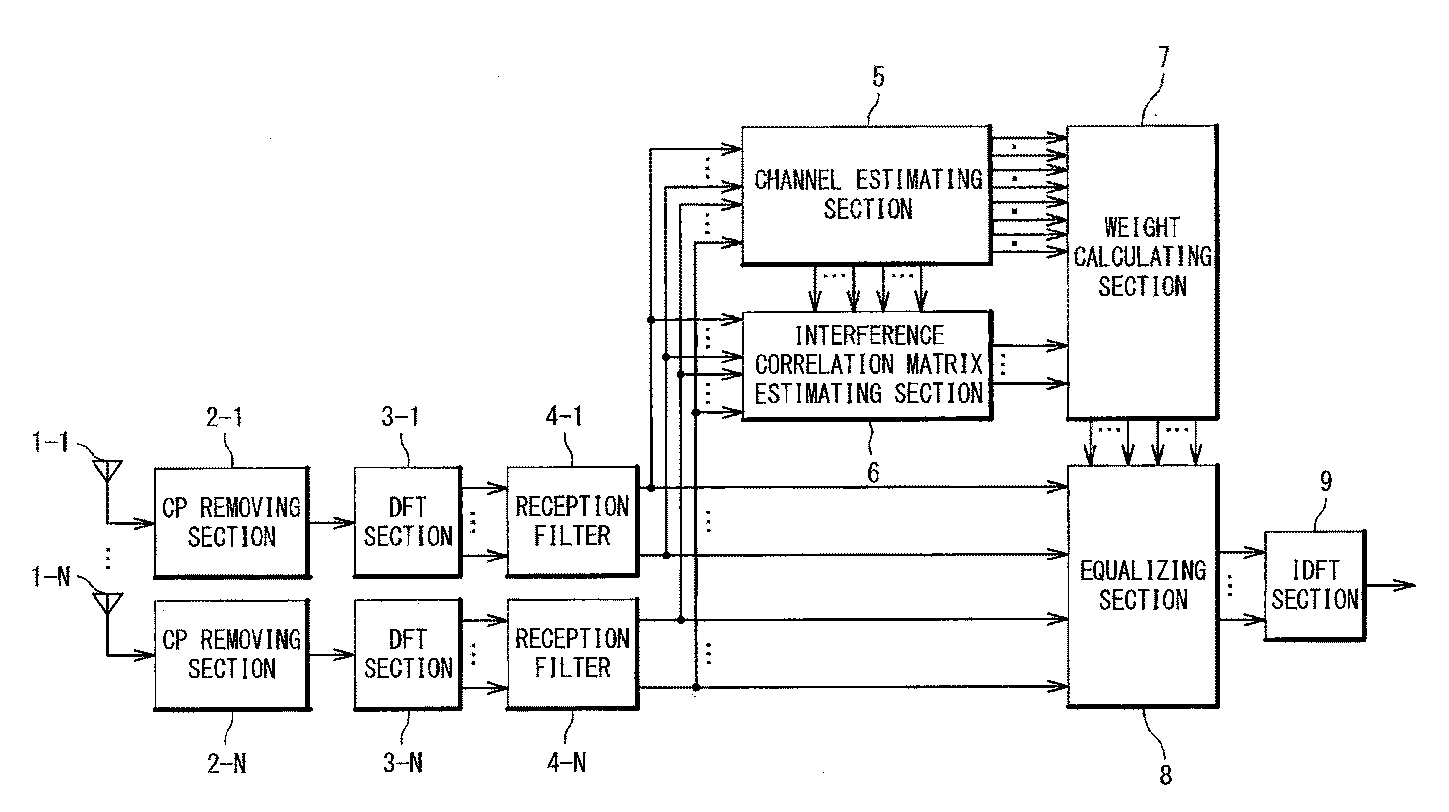
[0036]The receiving apparatus and the mobile communication system according to a first exemplary embodiment of the present invention will be described below with reference the drawings. FIG. 5 is a block diagram showing a configuration of the receiving apparatus according to the first exemplary embodiment of the present invention. The first exemplary embodiment relates to a receiving apparatus of a one-transmission antenna multiple-receiving antenna (SIMO: Single Input Multiple Output) communication. In the receiving apparatus of the present invention, an SC signal is received by N (N is the integer of 2 or more) receiving antennas and then multipath equalization and other cell interference suppression are carried out through a signal process in a frequency domain. The receiving apparatus of the present invention contains receiving antennas 1-1 to 1-N, CP removing sections 2-1 to 2-N, DFT sections 3-1 to 3-N, reception filters 4-1 to 4-3S, a channel estimating section 5, an interfer...

second exemplary embodiment

[0050]A second exemplary embodiment of the present invention will be described below. The second exemplary embodiment relates to the receiving apparatus of a multiple-transmission antenna multiple-reception antenna (MIMO: Multiple Input Multiple Output) communication.

[0051]FIG. 9 is a diagram showing the schema of the MIMO transmission / reception system. In the MIMO transmission / reception system, when the number of the transmission antennas is defined as M (M is an integer of 2 or more) and the number of the reception antennas is defined as N (N is an integer of 2 or more), the transmission side contains a transmitting unit 201 and transmission antennas 202-1 to 202-M, and the reception side contains reception antennas 203-1 to 203-N and a receiving unit 204. The plurality of transmission antennas 202-1 to 202-M transmit data signals that are different although the same frequency is used. The plurality of reception antennas 203-1 to 203-W are used to receive the data signals. Thus, w...


PUM


Abstract

A receiving apparatus is provided in which a single carrier signal is received by a plurality of receiving antennas, and multipath equalization and other cell interference suppression are carried out in a frequency domain at a same time. A plurality of antennas 1-1 to 1-N receives the single carrier signal. The DFT sections 3-1 to 3-N converts the reception signals into frequency domain signals. A channel estimating section 5 estimates a channel gain of a desired user signal by using pilot reception signals. An interference correlation matrix estimating section 6 estimates an interference correlation matrix from the pilot reception signals and a channel estimation value. A weight, calculating section. A weight calculating section 7 receives the channel estimates and the interference correlation matrix and calculates equalization weights. An equalising section 8 performs multipath equalization and other cell interference suppression to the desired user signal in a frequency domain. An IDFT section 9 converts an equalization signal into a signal in a time domain.

Description

TECHNICAL FIELD[0001]The present, invention relates to a receiving apparatus and a mobile communication system, and more particularly, relates to a receiving apparatus and a mobile communication system in which a single carrier signal is received by a plurality of receiving antennas.[0002]It should be noted that the present patent application claims a priority on convention based on Japanese Patent Application No. 2007-010977 and the disclosure thereof is incorporated herein by reference.BACKGROUND ART[0003]In an uplink wireless system of a next generation mobile communication, a high transmission power efficiency needs to be attained in order to enlarge a communication area, Thus, a single-carrier (SC) system in which a peak to average power ratio (PAPR) is low is considered to be dominant. Also, in the next generation mobile communication, it is important to attain a high-speed data transmission. When an SC signal is used to carry out the high-speed data transmission, a problem of...

Claims


Application Information

Patent Timeline
IPC IPC(8): H04B15/00H03D1/04H04B1/707H04J99/00
CPCH04B1/71052H04B1/712H04B7/0854H04L2025/03414H04L25/03159H04L27/2647H04L25/0228H04B7/0413H04L25/0224
Inventor YOSHIDA, SHOUSEIKIMATA, MASAYUKI
Owner NEC CORP
Why Eureka
Try Eureka