Massage devices

Inactive Publication Date: 2010-02-25
LOREAL SA
View PDF12 Cites 33 Cited by
  • Summary
  • Abstract
  • Description
  • Claims
  • Application Information

AI Technical Summary

Benefits of technology

[0008]There exists a need to improve massage devices still further, in parti

Problems solved by technology

Such a device is of relatively complex structure and requires the forks to be made in s

Method used


Image

  • Massage devices
  • Massage devices
  • Massage devices

Examples


Embodiment Construction

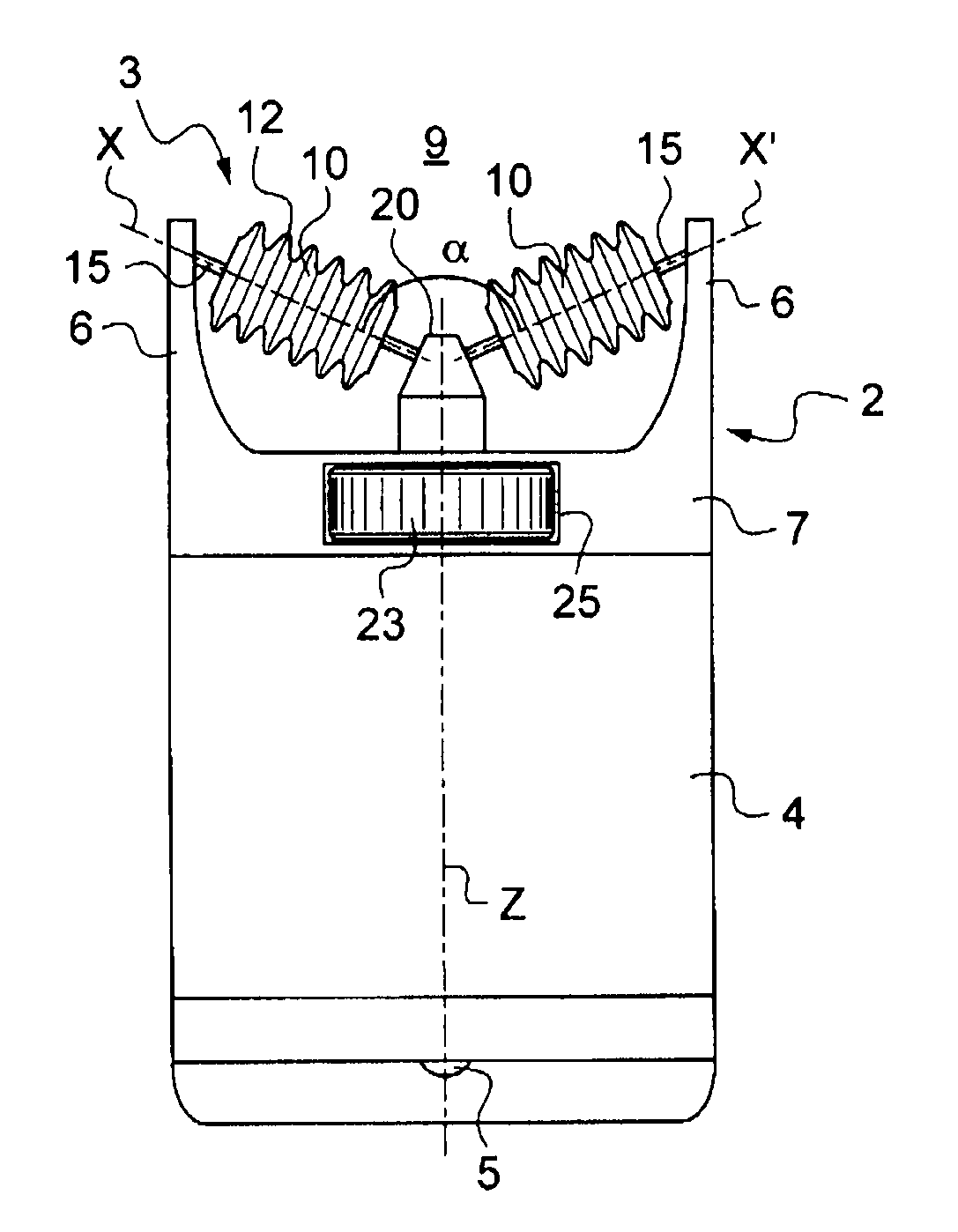
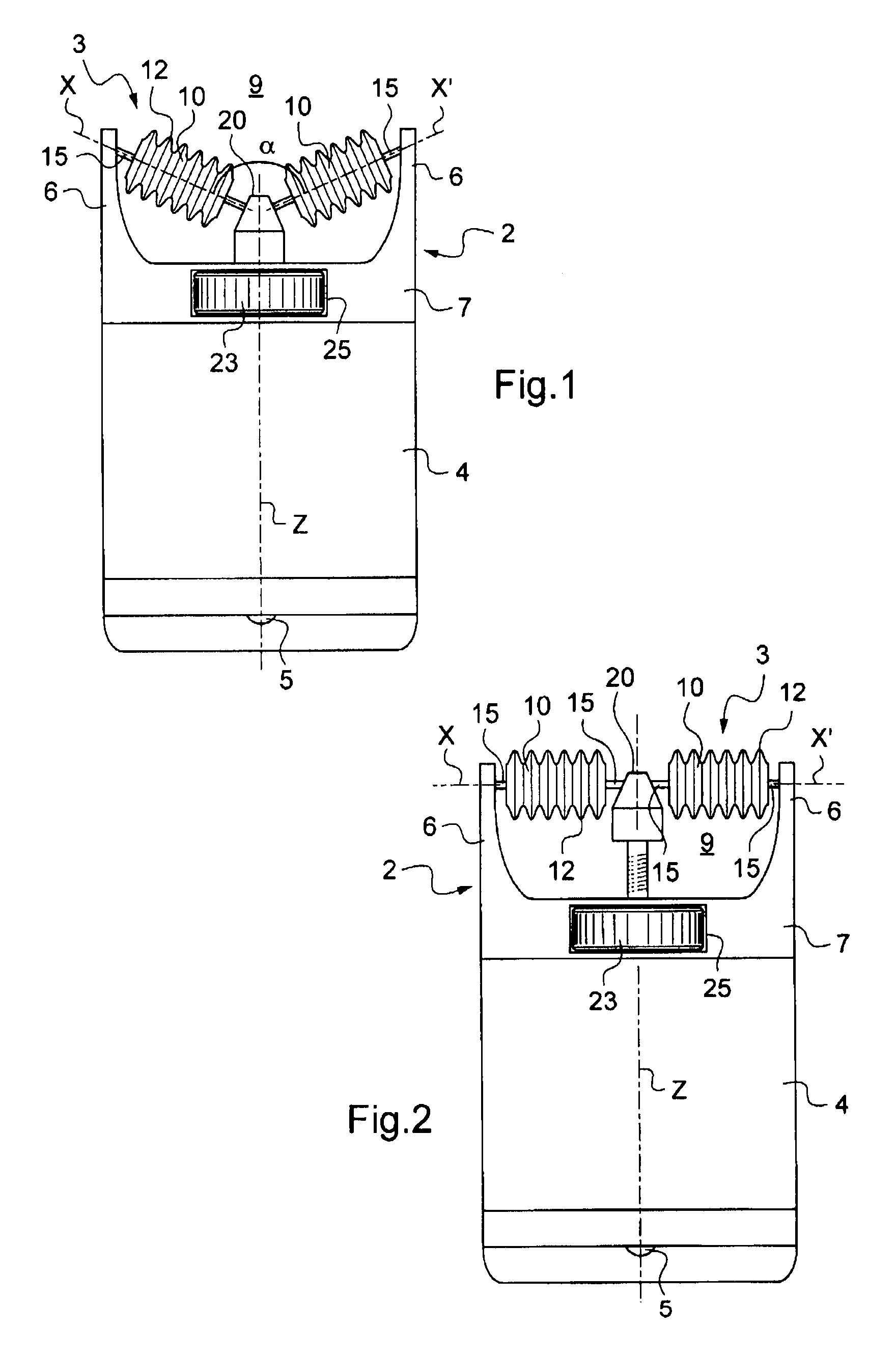
[0075]The massage device 1 shown in FIGS. 1 and 2 includes a support 2 and a massage system 3.

[0076]In the embodiment under consideration, the support 2 is secured to a container 4 that contains a composition that is suitable for being applied to the skin before, during, or after massaging. By way of example, the container 4 includes a composition dispenser system that may be of any type, and in the embodiment under consideration the container may be closed by a cover 5 present at the rear of the device 1, at its end remote from the massage system 3.

[0077]The dispenser system may include an endpiece, a foam, an applicator roller or ball, a pump, or any other known means for dispensing and / or applying the composition.

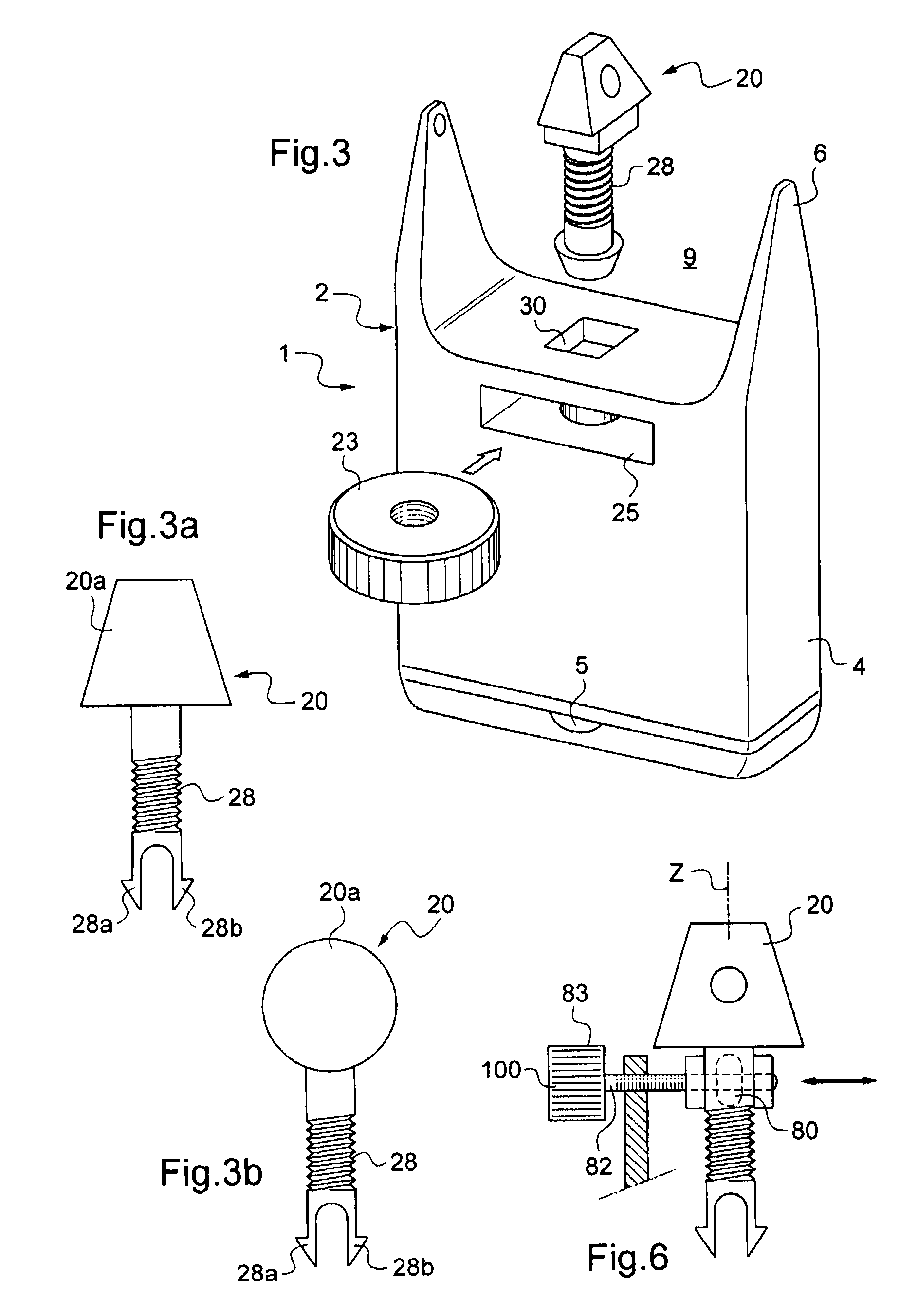
[0078]In the embodiment under consideration, the support 2 is stationary relative to the container 4, and, by way of example, includes a base 7 that is fastened by snap-fastening, or by some other means, on the container 4.

[0079]As in the embodiment shown, the container ...


PUM


Abstract

The present invention relates to a massage device including at least one rotary massage system (3), the device comprising:
    • a support (2) including two mounting pieces (6); and
    • two massage members (10) mounted on said support and each turning relative to the support (2) about an axis of rotation (X, X′) defined by a shaft (15), each mounting piece (6) supporting the shaft (15) associated with the corresponding massage member, the slope of the axes of rotation (X, X′) relative to the mounting pieces (6) depending on the position of an intermediate part (20) that is movable relative to the support (2), said intermediate part being situated between the massage members (10) and being connected to the shaft (15) associated with each massage member.

Description

[0001]This non provisional application claims the benefit of French Application No. 08 55264 filed on Jul. 30, 2008.BACKGROUND OF THE INVENTION[0002]US 2007 / 0083135 A1 discloses a massage device including two rotary massage members that are carried by flexible branches.[0003]EP 1 774 950 discloses another massage device including massage members each having at least one pair of flexible lips.[0004]Massage devices including rollers are described in FR 1 093 828, FR 2 480 118, FR 2 854 312, GB 880 289, and GB 519 875.[0005]EP 1 472 953 A1 discloses a massage device including two massage rollers each mounted on a fork, with an adjuster system for adjusting the orientation of one fork relative to the other. Such a device is of relatively complex structure and requires the forks to be made in such a manner as to withstand relatively large mechanical forces on the adjuster system.[0006]FR 2 664 158 also describes support forks for supporting the massage rollers.[0007]FR 2 919 493 provides...

Claims


Application Information

Patent Timeline
IPC IPC(8): A61H15/00
CPCA45D34/041A61H15/0092A61H2201/1695A61H2201/105A61H2015/0057
Inventor GUERET, JEAN-LOUIS
Owner LOREAL SA
Why Eureka
Try Eureka